Back in May of 2026 I got my hands on a 1999 Daytona 955i that someone had attempted to turn into a restomod cafe racer of sorts, but ultimately had given up on pretty early on.
I came across quite a few challenges, made custom parts and generally had to figure out quite a lot of stuff along the way.
So I figured documenting my journey would be worth while for anyone looking to or currently converting their Daytona to a Speed Triple.
I will add many pictures throughout this page, however to prevent making this page any longer of a scroll than it already is I have hidden a bunch of them in little drop downs which you can unfold by clicking on them.
Index:
- Arrival
- Indexing
- Identifying Issues
- Fuel Connectors
- Indicators
- Horn
- Mirrors
- Broken Plastics
- Coolant (leaks)
- Exhaust
- Brake Sensor
- Clutch Cable
- Battery And Tray
- Wiring Shennanigans
- IACV
- Idle Issues
- Custom Parts
- Current To-Do and future plans
Arrival
To keep a long story short, the way it got to me is through a friend.
He was kind enough to deliver the bike to me by trailer (against compensation) and handle the transaction with the original owner (friend of the friend).
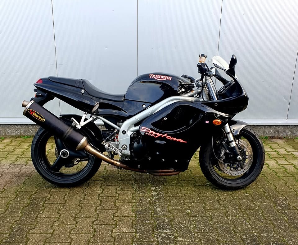
Here is a picture I found of what the bike looked like when the previous owner bought it:
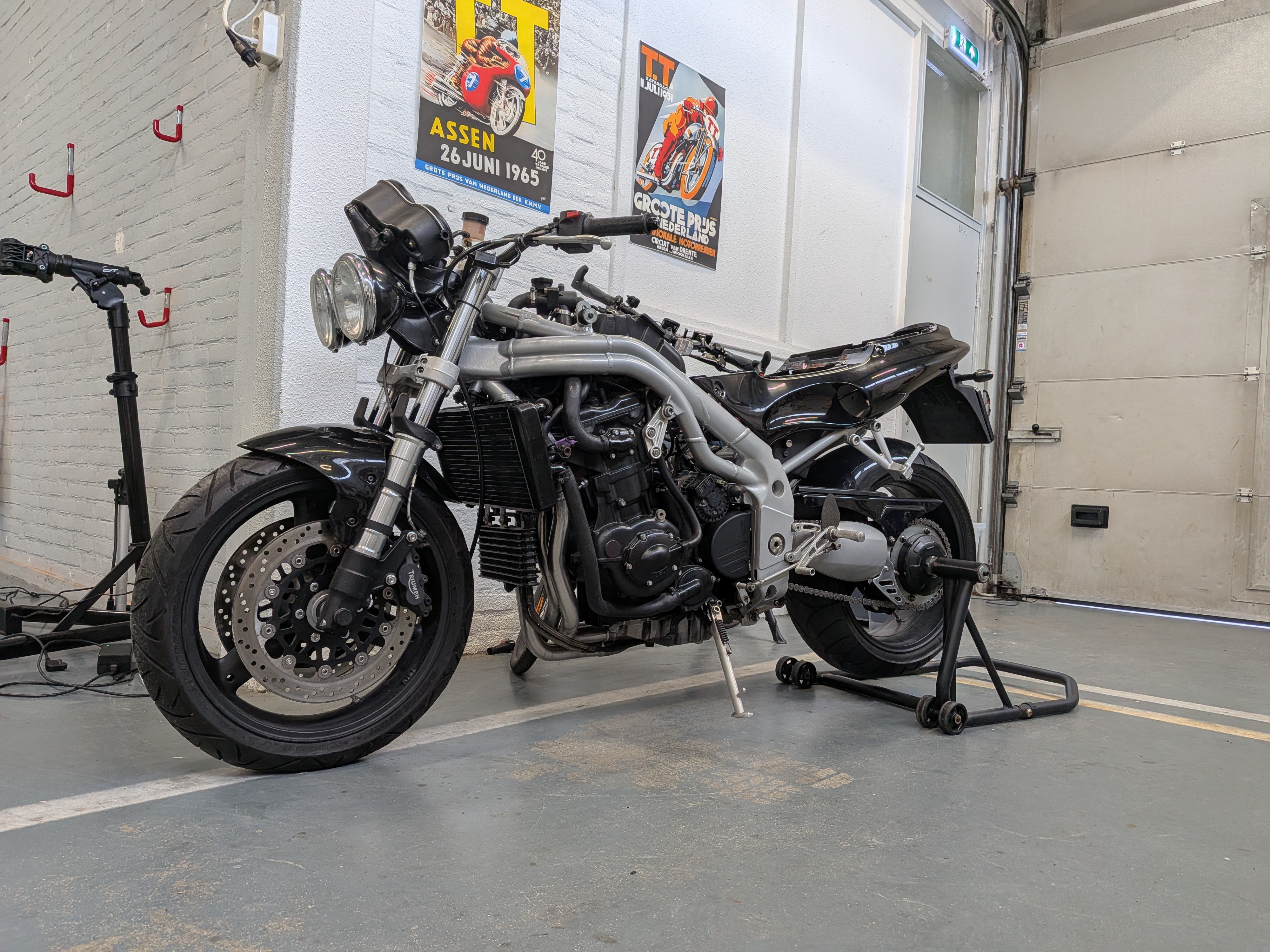
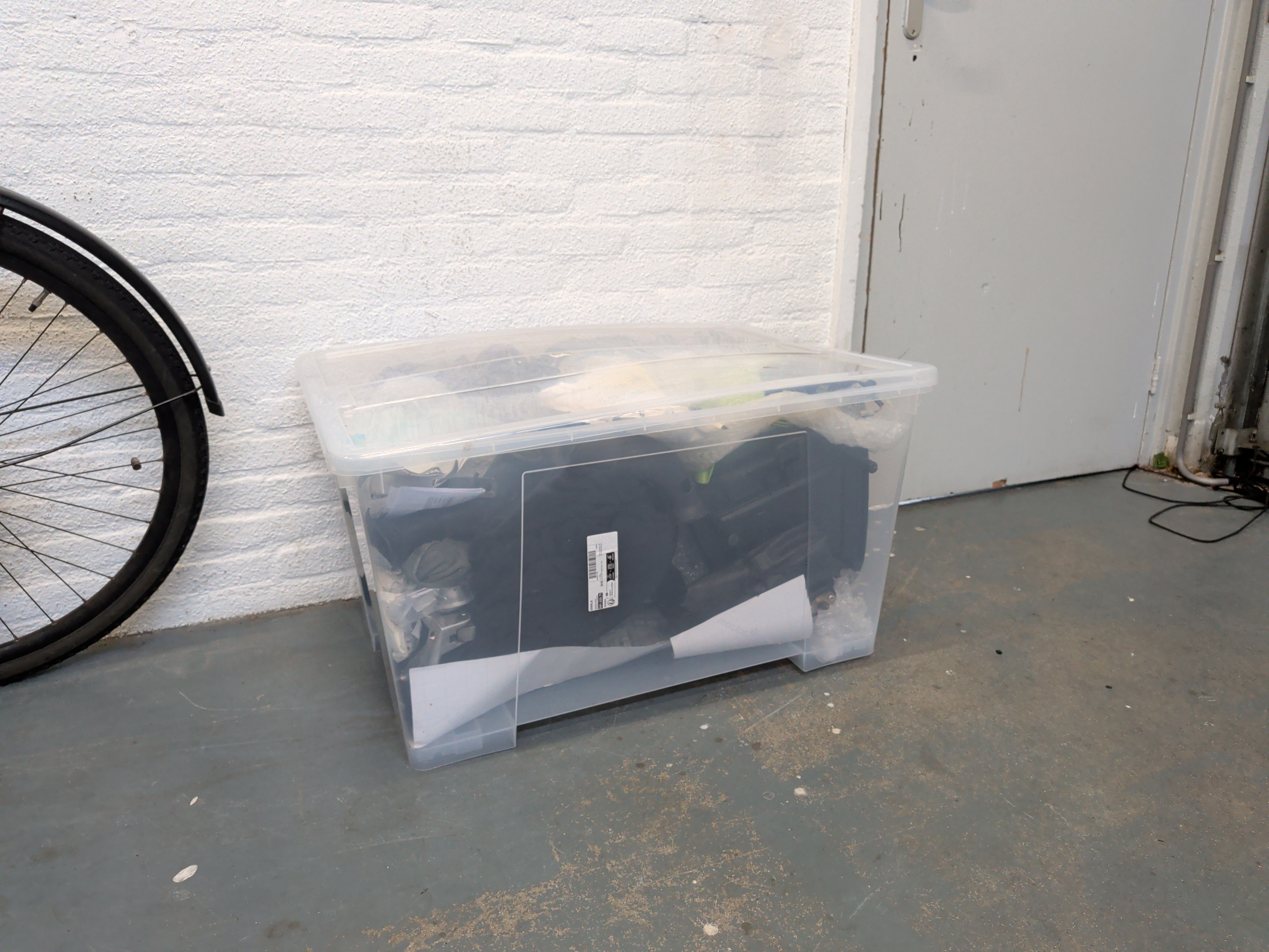
And here is a picture of how it arrived at my place, along side a big bin full of parts:
Additional photos of when it first arrived
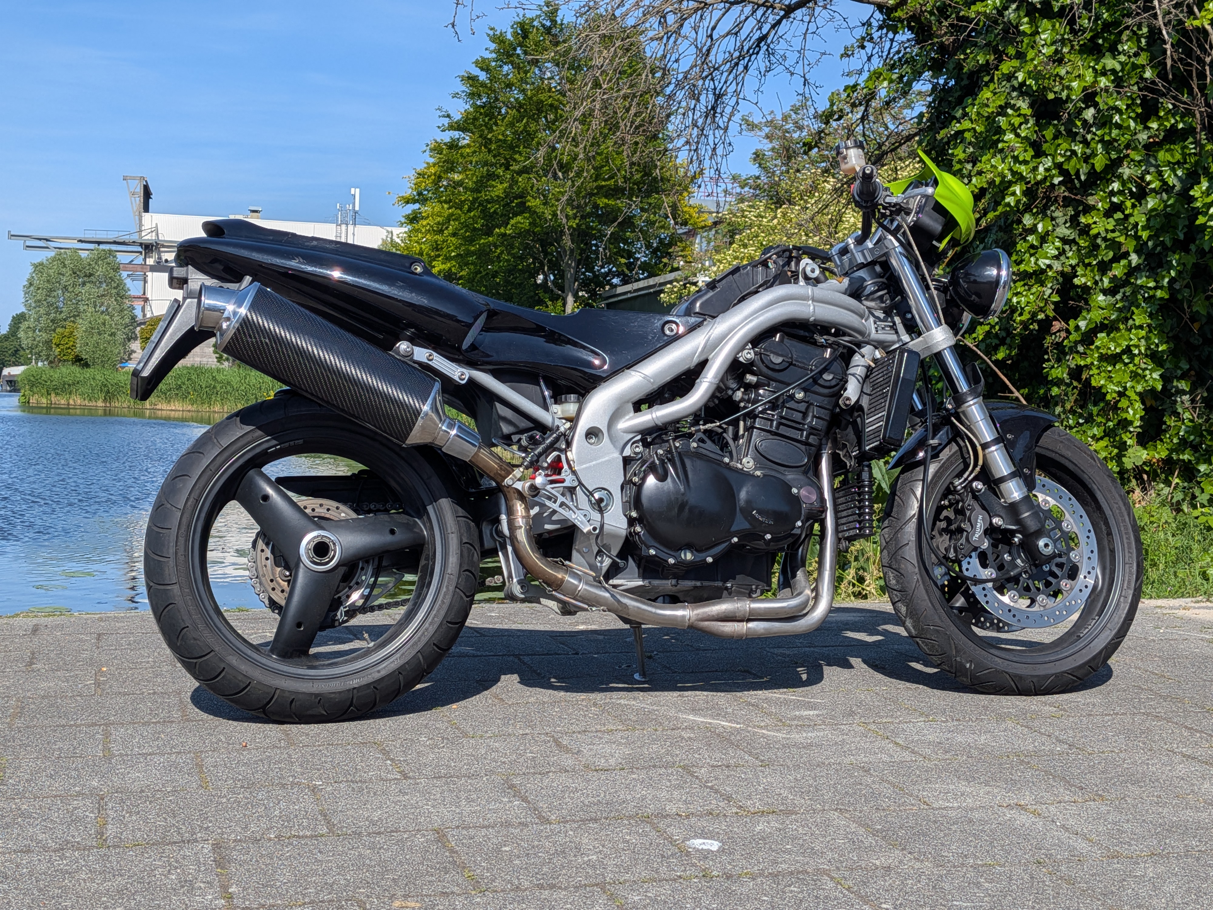
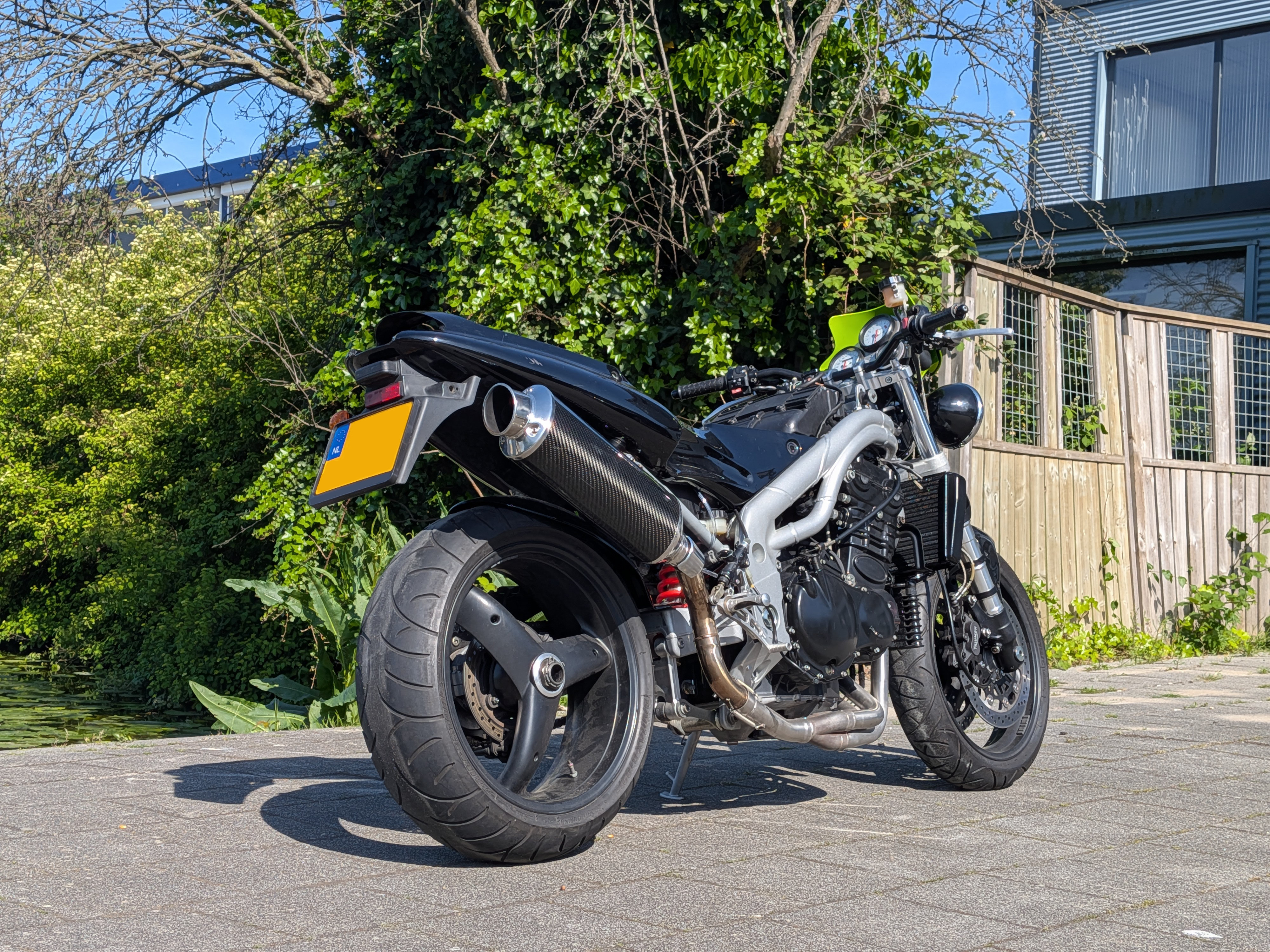
Right click or long press to view full-size image in a new tab
Indexing
After letting my excitement cool off a little bit I started unpacking everything and actually indexing what I had received.
It was advertised as a 1999 T595 Daytona, however upon closer examination it is actually a Daytona 955i as indicated by the VIN and registration plate.
It also came with a paddock stand included! (lovely bonus)
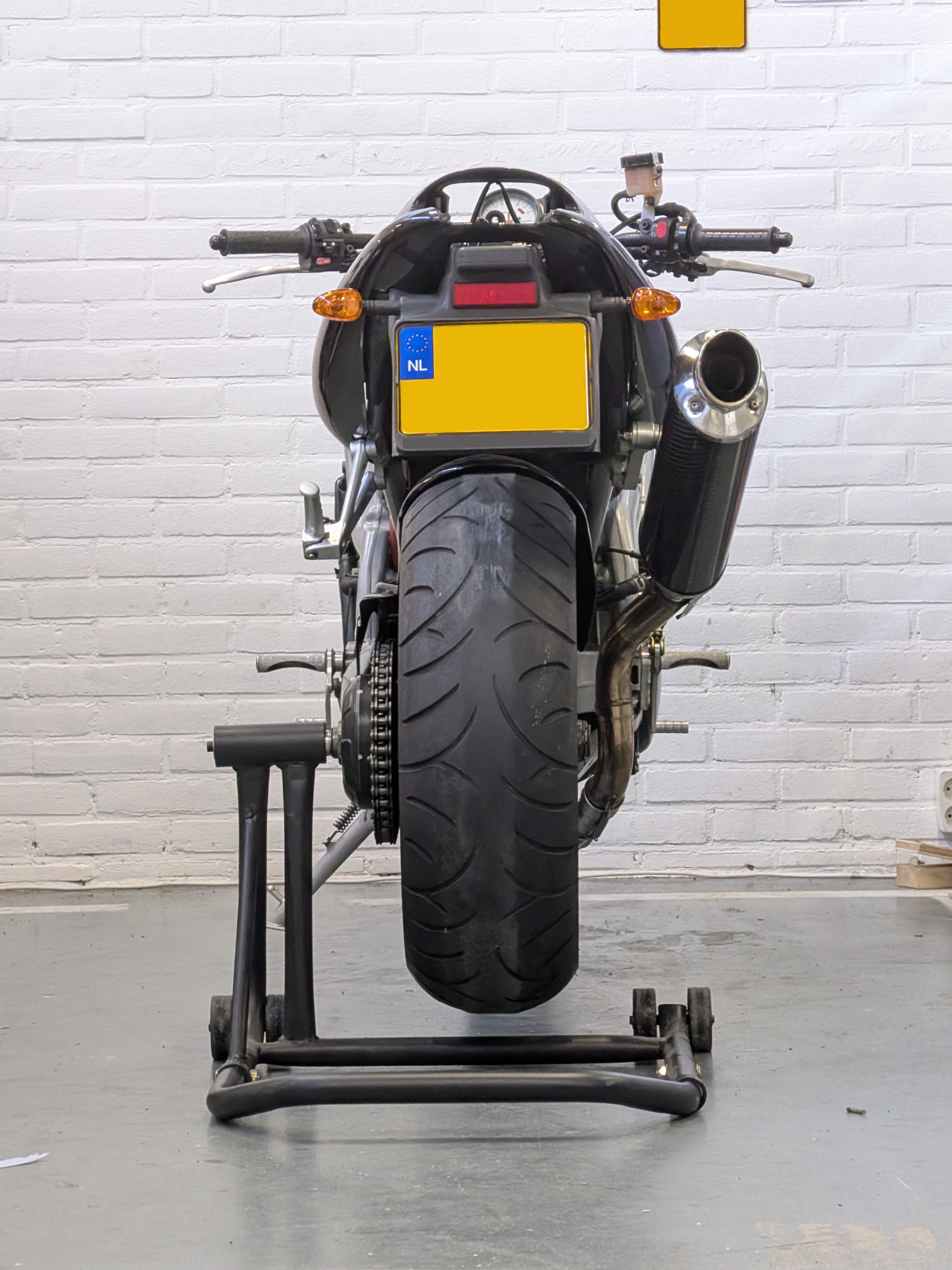
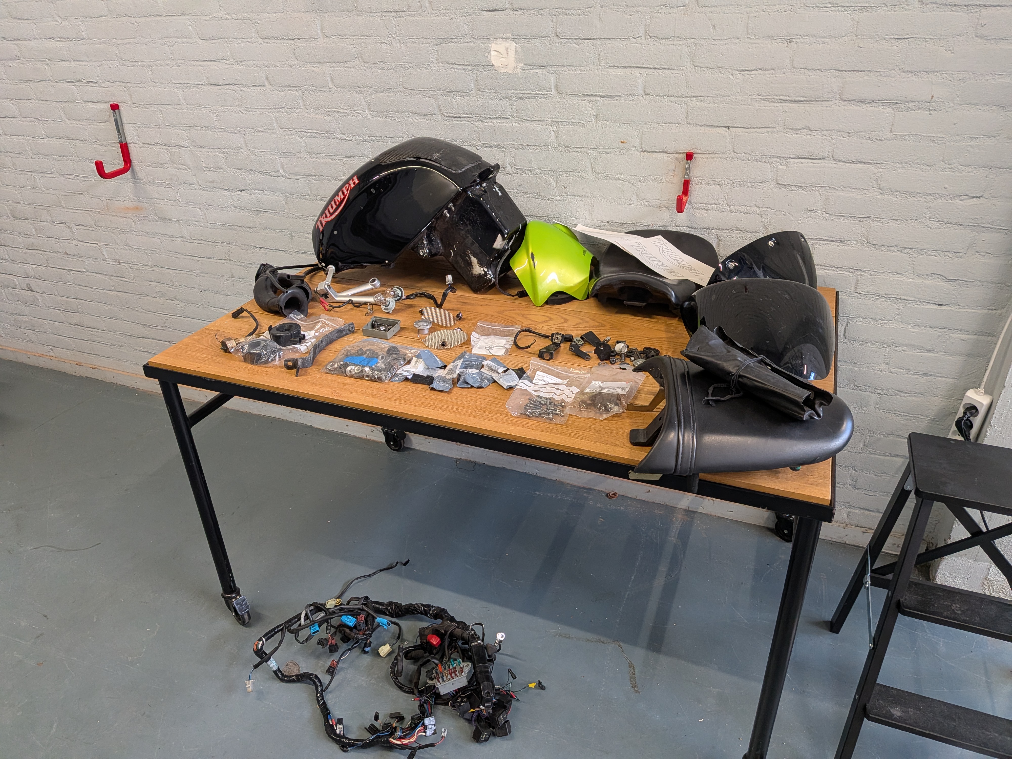
Now let’s go through the stuff and see what all it came with in the bins:
- Fuel tank
- Seat
- Passenger seat
- Rear cowl
- Flyscreen (front fairing)
- Front gas tank cover
- Bags of hardware
- Daytona fairing brackets
- Original toolkit
- Airbox intake hoses (Daytona)
And here is a list of all the items that had gone missing at the previous owners place:
- Battery
- Battery strap
- Fairings
- Taillight
- Front indicators (makes sense)
- Mirrors (makes sense)
- Horn
- Bolts
- Nuts
- Washers
- Rubber grommets
- Vent hoses
The list of (myserious) included extras:
- New rubber headlight piece (headlights both have new ones already)
- New rear wheel locking ring (old one is still fine)
- 6x new exhaust nuts (there are 6 brand new ones installed already)
- Top yoke nut (not a clue why there is a spare)
- Broken fuel sensor
- Mysterious wiring extensions
- A complete Daytona 955i Wiring harness
Identifying Issues
I could write quite a long section here, however I have opted to make a list of bullet points, I’ll go into detail on some of them later on down the page.
After examining the bike and working on it for a while I came across the following issues:
- Fuel connectors busted
- Battery missing
- Battery wires both red
- How to mount the front indicators
- No mirrors
- No horn
- No rear light
- 20 year old tires
- Missing nuts and bolts
- Majorly leaking fork seal
- No/very low coolant level
- Coolant leaks
- Impossibly hard to pull clutch lever
- Seized up clutch
- Stiff to change gears
- Speedometer cable hitting the headlight bracket
- Headlights being loose
- Blown fuse
- Burnt out headlight
- Engine warning light
- Broken foot guard
- Broken rear brake light sensor
- Busted chain guard/rear mud guard
- Battery tray too tall
- TOR exhaust too loud (personal preference)
- Mushy brake feel
- Crusty IACV hoses
- Bubbling fuel tank (of course)
- Various things not bolted down or barely hand tight
- Broken foot guard
Ain’t that a list and a half… now for some more positive takes to keep up the spirit up:
- The bike was mostly complete
- The bike is remarkably clean
- The engine ended up running just fine
- All the electrics ended up being fine
- The alternator and rectifier appear to work fine at a nice 14.1v at idle
- I learned a hell of a lot about the bike
Here is a quick clip of me starting it for the very first time with some brake cleaner to test for signs of life:
Fuel Connectors
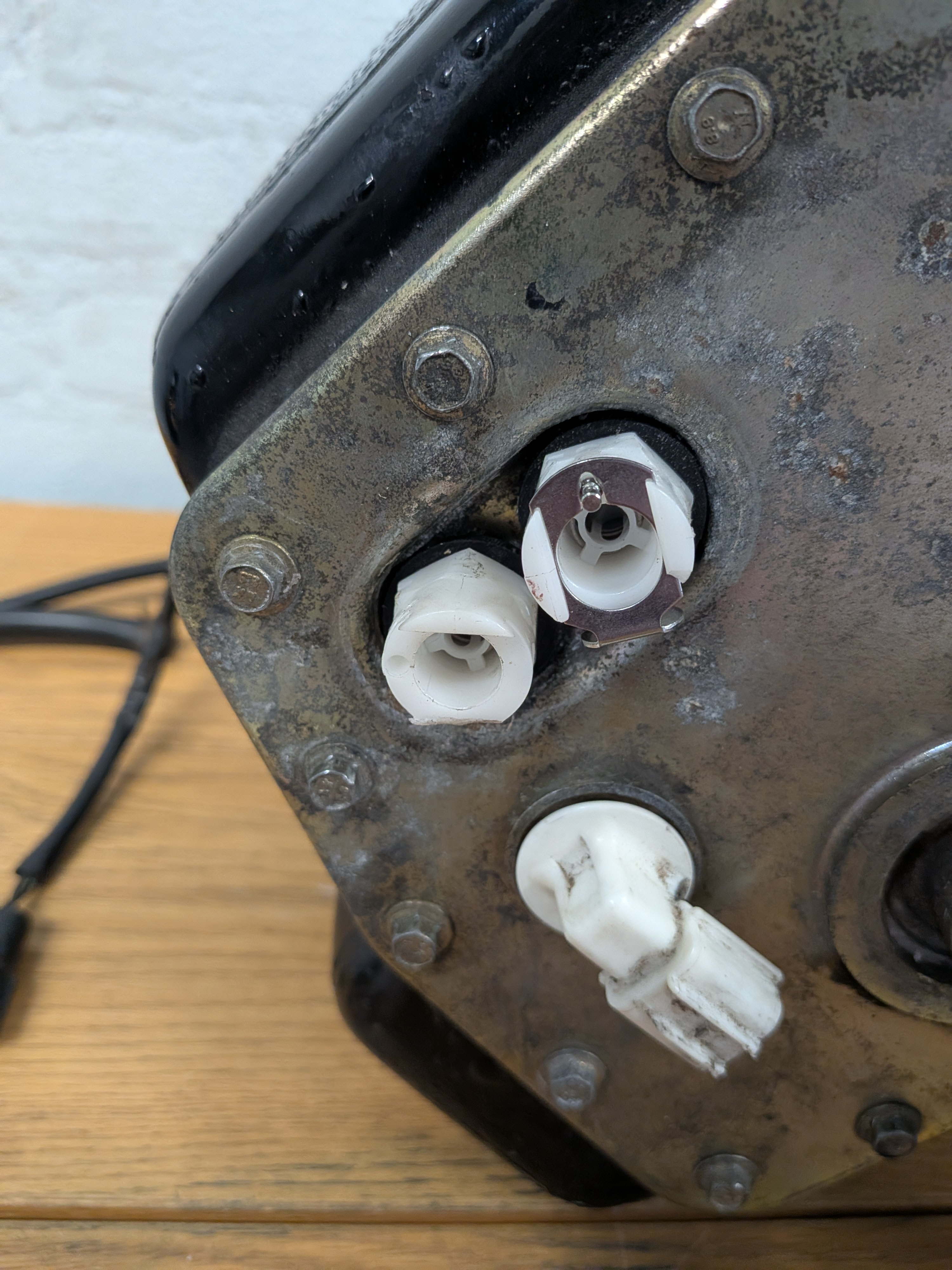
Oh the dreaded, or shall I say dreadfull (but kinda awesome when not broken) fuel connectors.
As the saying goes: If yours haven’t broken yet it’s not a matter of if, it’s a matter of when. And it all just comes down to old brittle plastics being… well… old and brittle.
Mine were also very much busted, luckily I was still able to thread them out without too much of a struggle, but then came sourcing replacements.
What a weird process that was, every supplier I looked at was charging anywhere from $50 to $80 PER CONNECTOR, which I thought was absolutely ridiculous.
I really did not want to get anything from AliExpress, as quite honestly when it comes to a pressurized fuel system I don’t trust them.
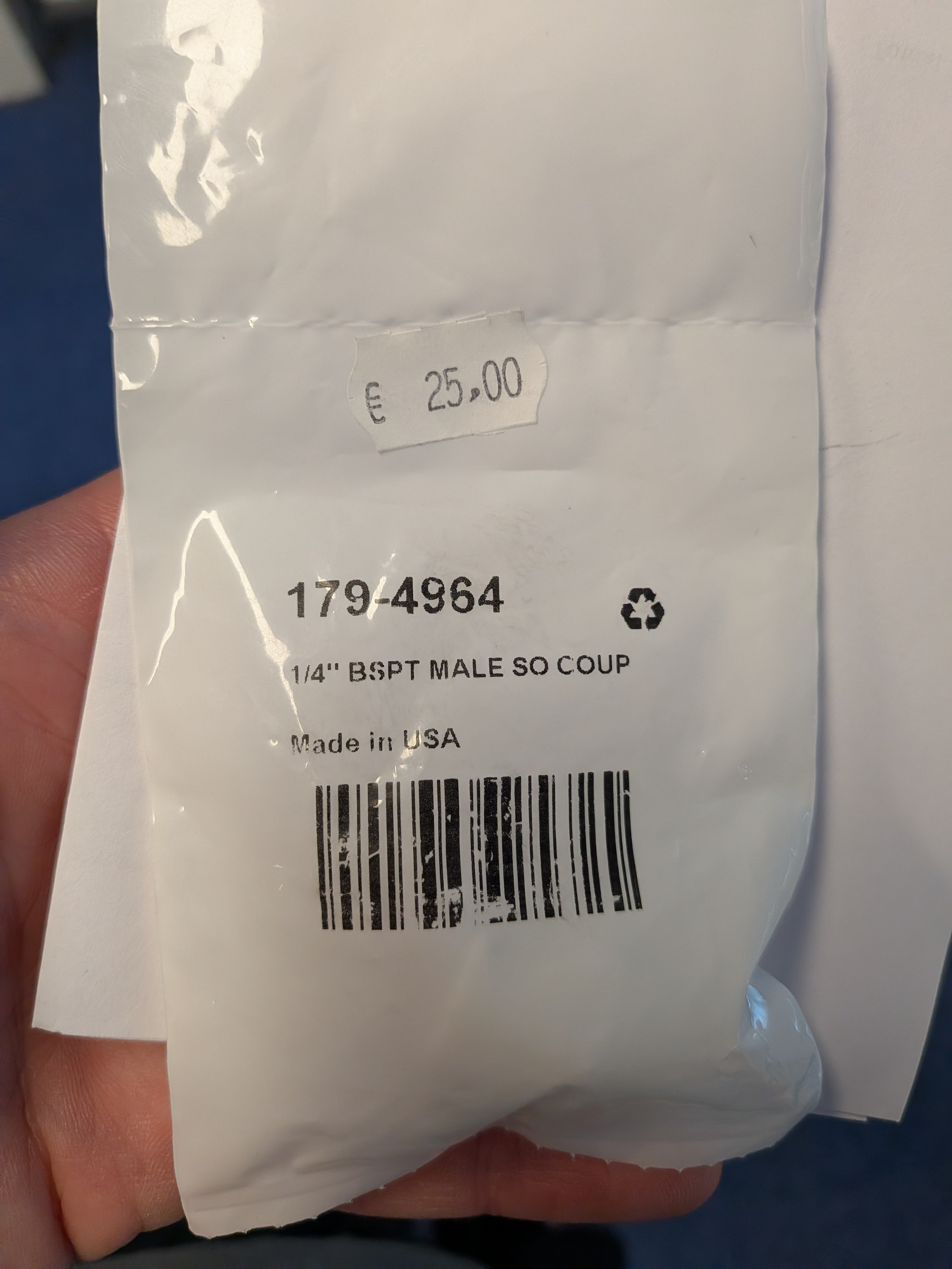
After some more looking I found a shop selling it for $33 which seemed more reasonable (packaging said $25 on it when it arrived, bit pissed about that). Upon receiving the replacement (a genuine CPC coupler) I decided to look up the model number and see if any industrial suppliers sell these.
Turns out they do! And funnily enough these couplers are also commonly used on liquid vending machines and industrial hydraulic solutions! This also meant there were plenty of suppliers for them.
The original part number from CPC is: PLCD10004BSPT for the plastic variant and LCD10004BSPT for the metal version, costing €19,11 and €46,21 respectively (including VAT at RS-Online).
And then to imagine they cost between $50-80 for the plastic one and $60-$90 for the metal ones at most motorcycle stores I checked… yikes!
Here’s a quick video of the very first startup on it’s own fuel (old fuel at that):
Indicators
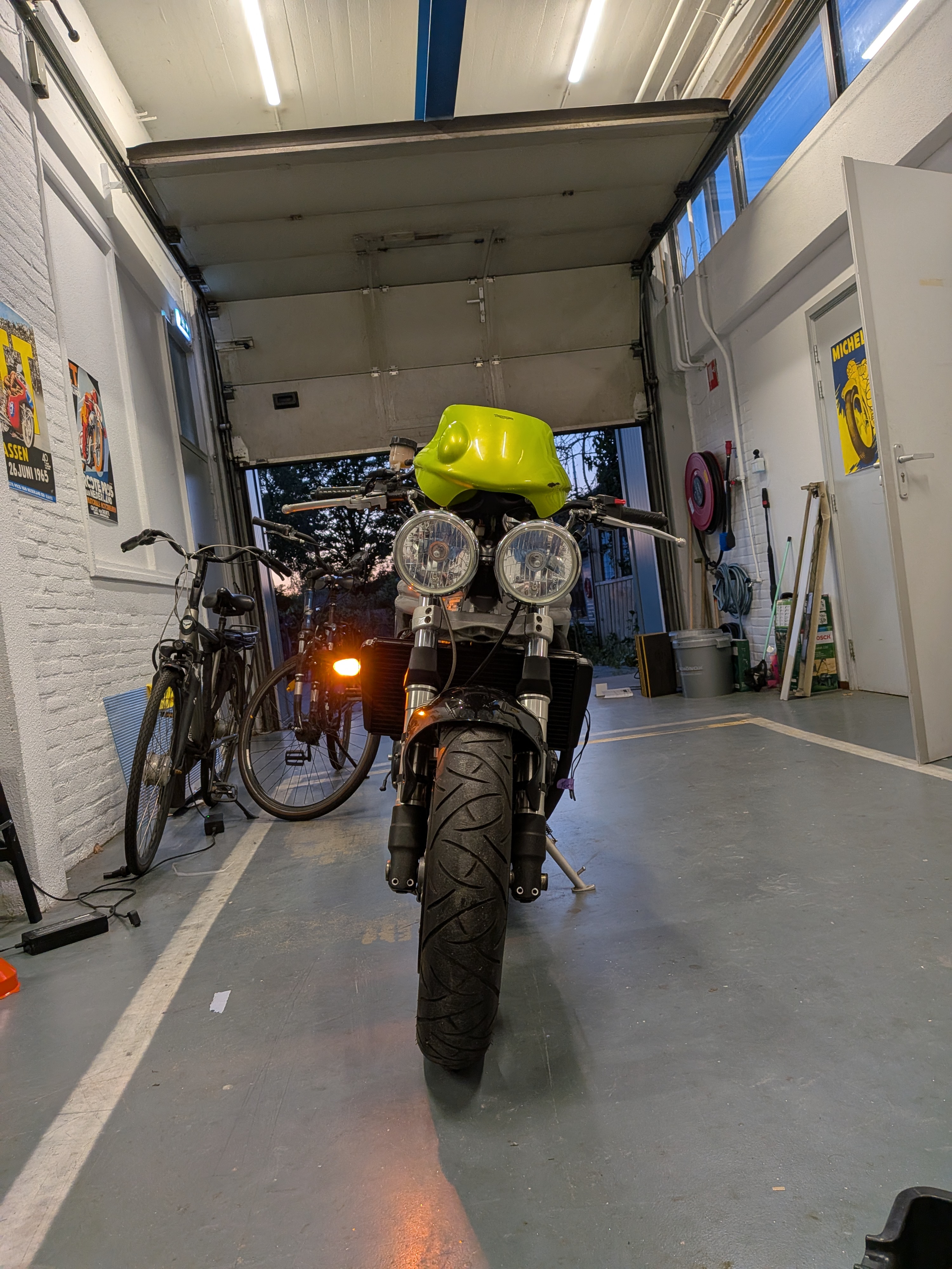
This problem was a real head scratcher for a second, as the Daytona originally has it’s indicators integrated into the fairings.
The speed triple on the other hand has them attached directly to the radiator (threaded inserts), problem is that whilst the bikes are damn near identical in almost every aspect, as well as having an almost exact 1:1 looking radiator setup, the Daytona radiators do not have the threaded inserts.
This really left me scratching my head as to how to solve this.
My original options were:
- Fork tube mounted indicators (didn’t think it’d look good)
- Mounting them near/around the headlight (custom and not great looking)
- Designing custom clamps for the radiator (tedious and could harm the radiator)
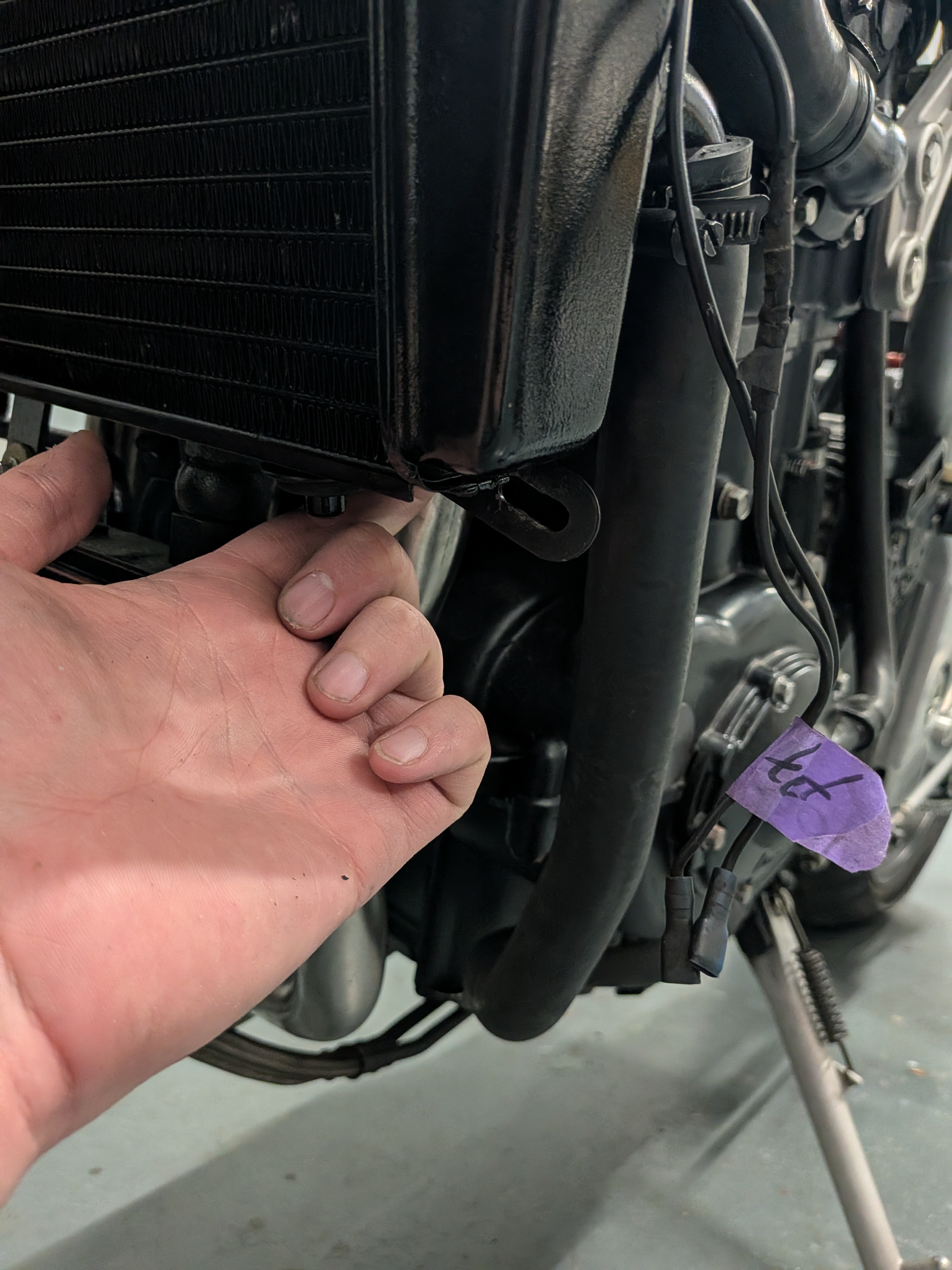
Eventually I came up with a better solution after digging through the bin of parts that the bike came with, namely the original Daytona fairing brackets!
There were 2 brackets in particular that were almost the exact perfect length and when bolted to the engine mount would put them right in the spot where the original Speed Triple indicators would go!
So I took a file, opened up the one side to fit an indicator through it, took out the engine mount bolt, put it in between and torqued it all back down. And the end result is just perfect.
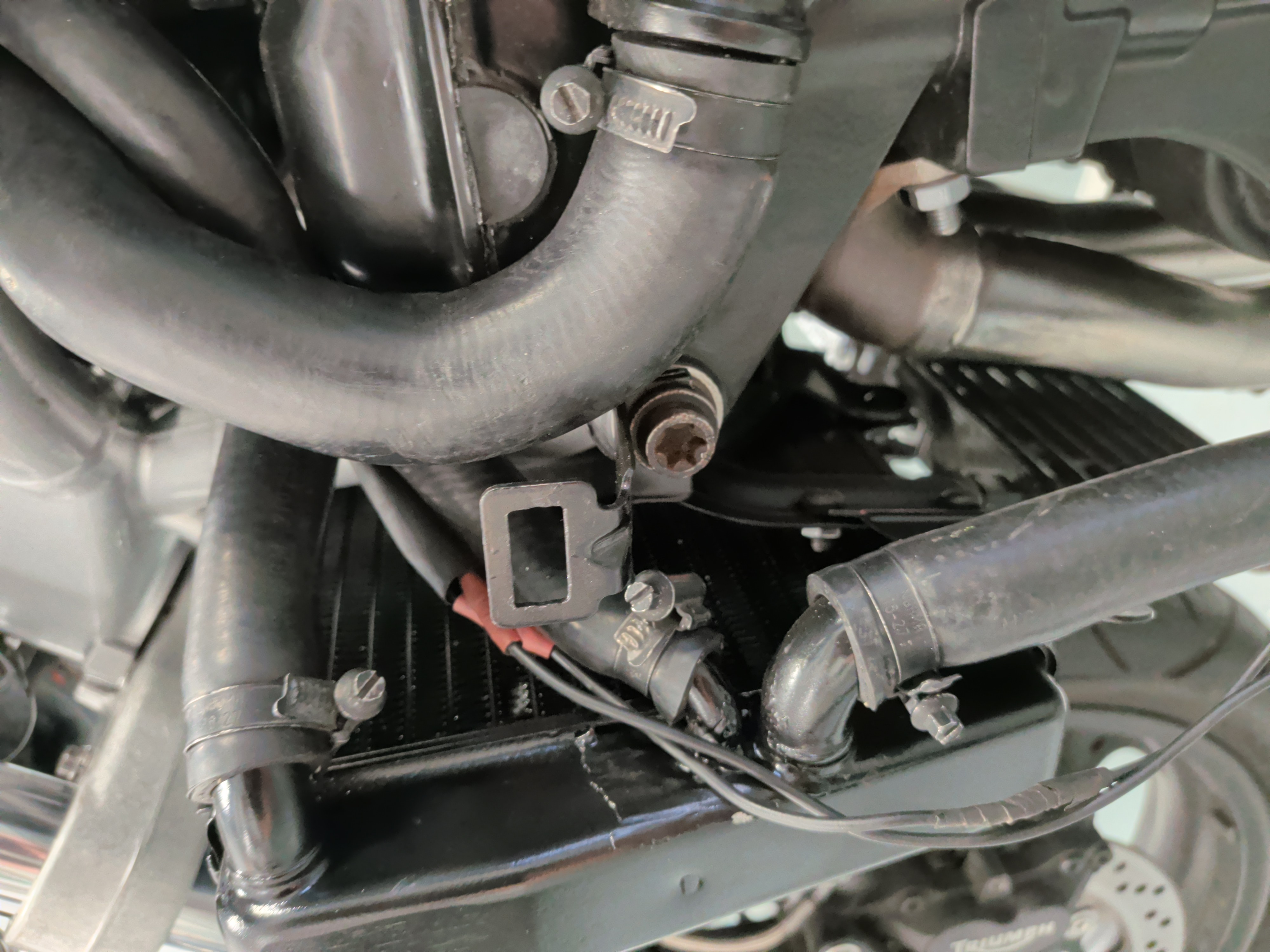
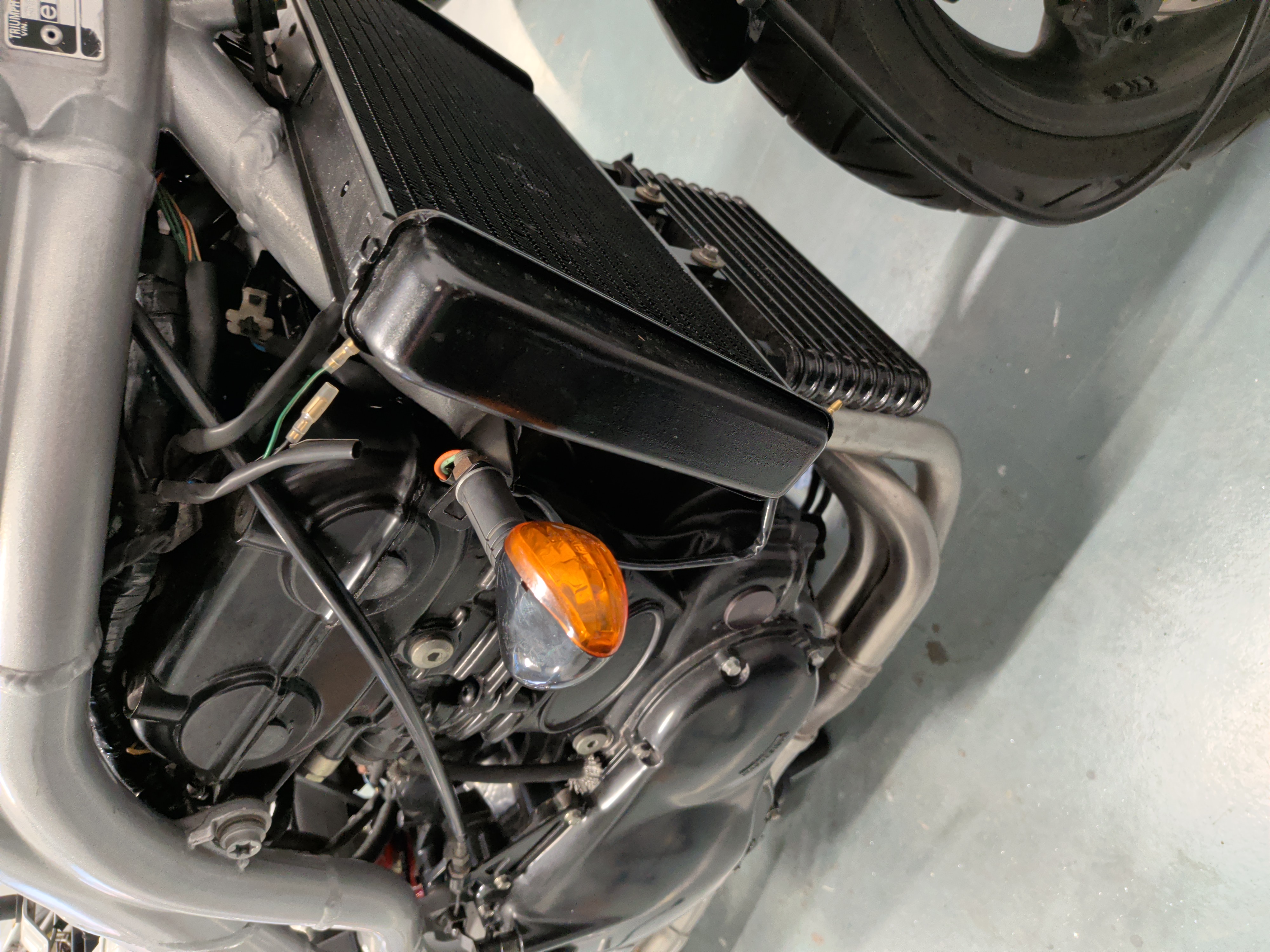
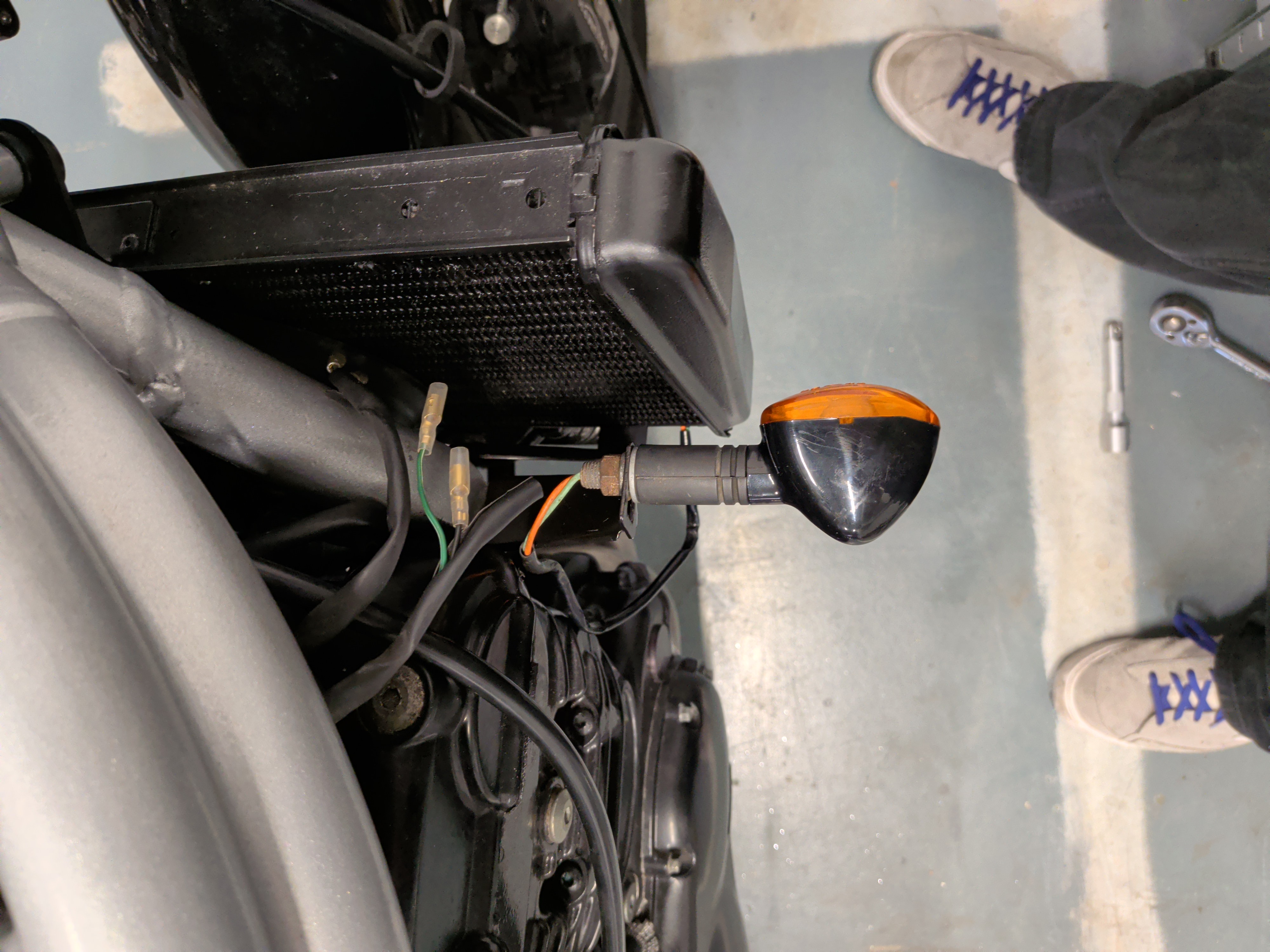
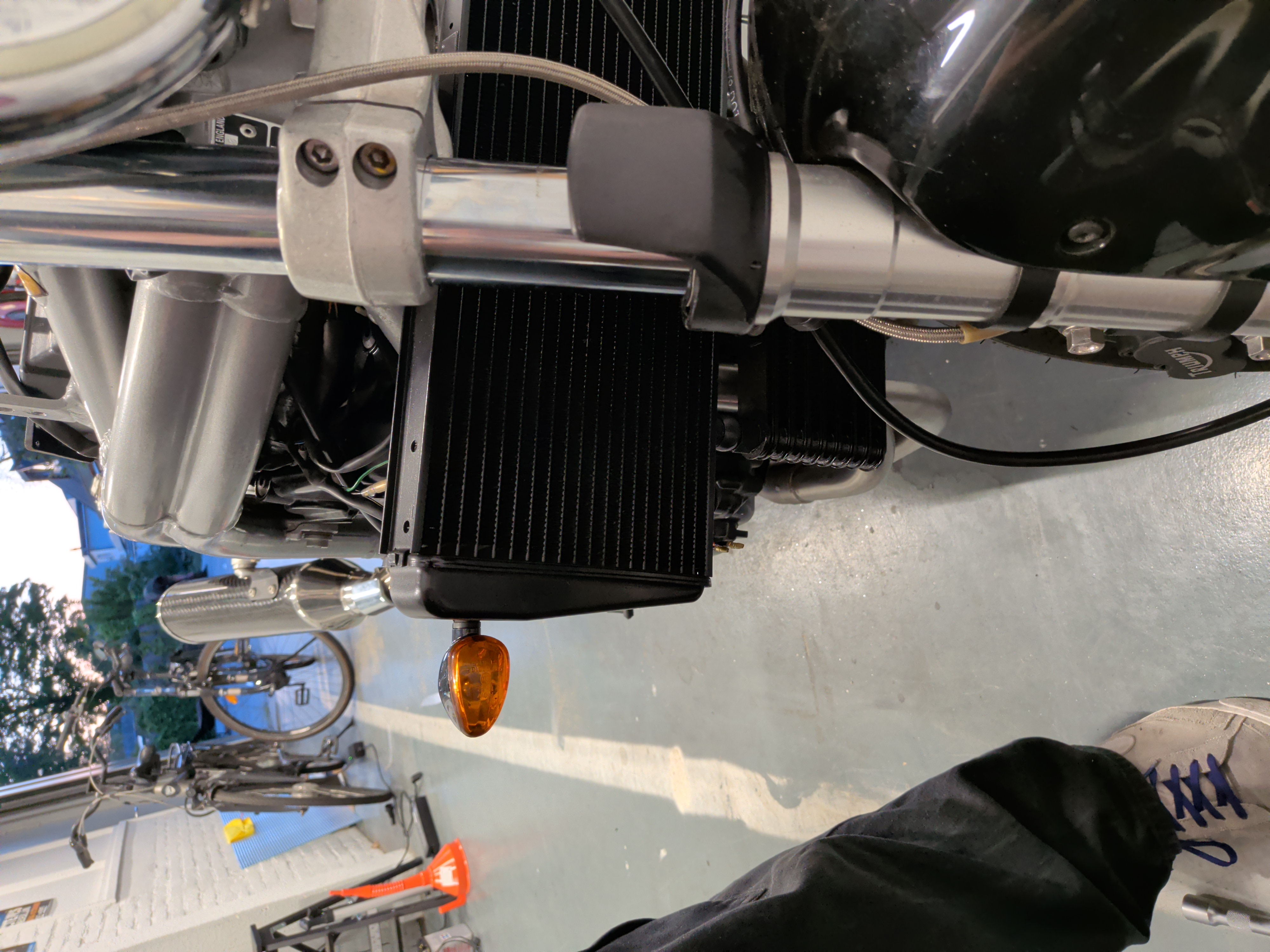
Additional photos of the indicators.
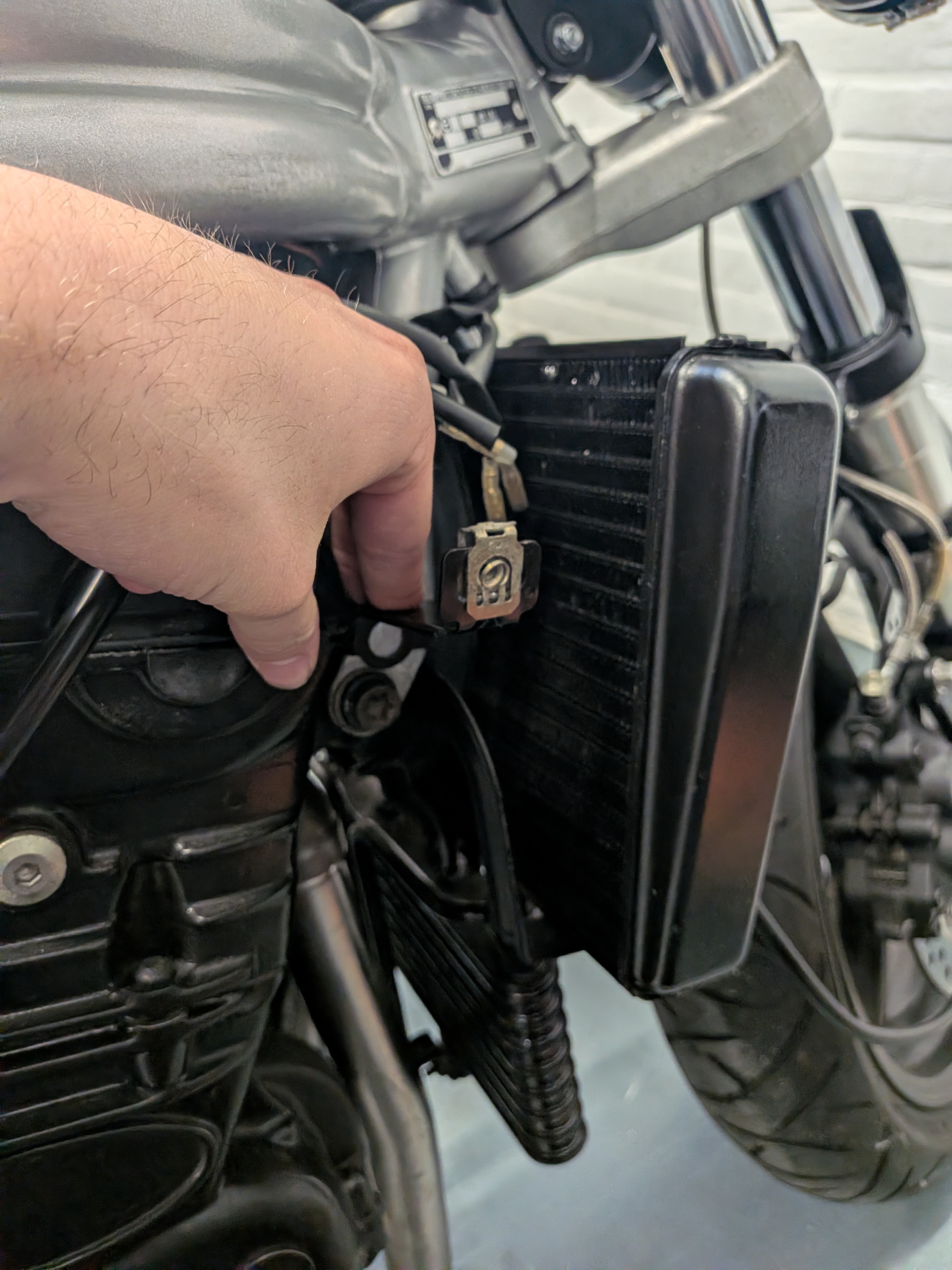
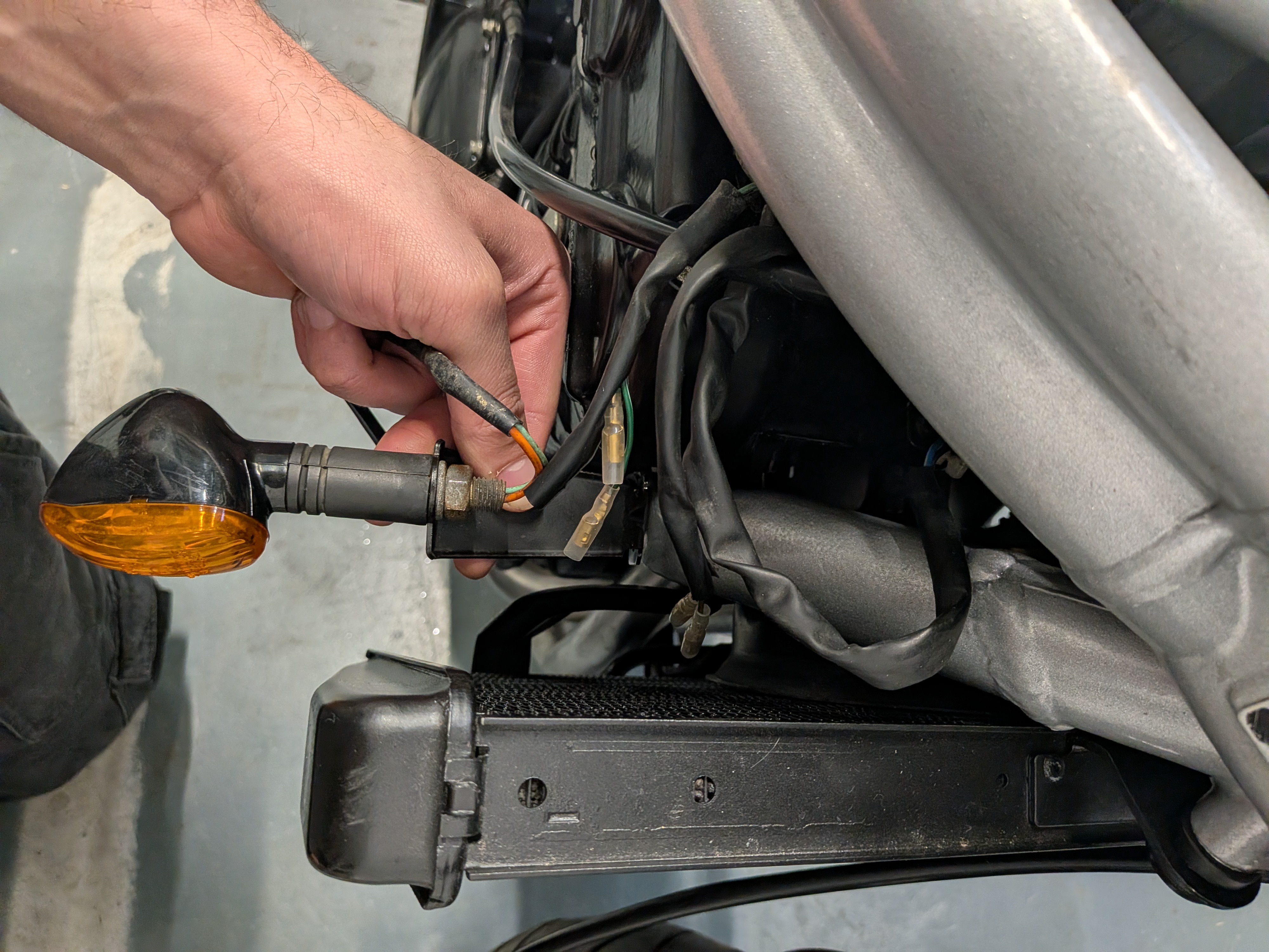
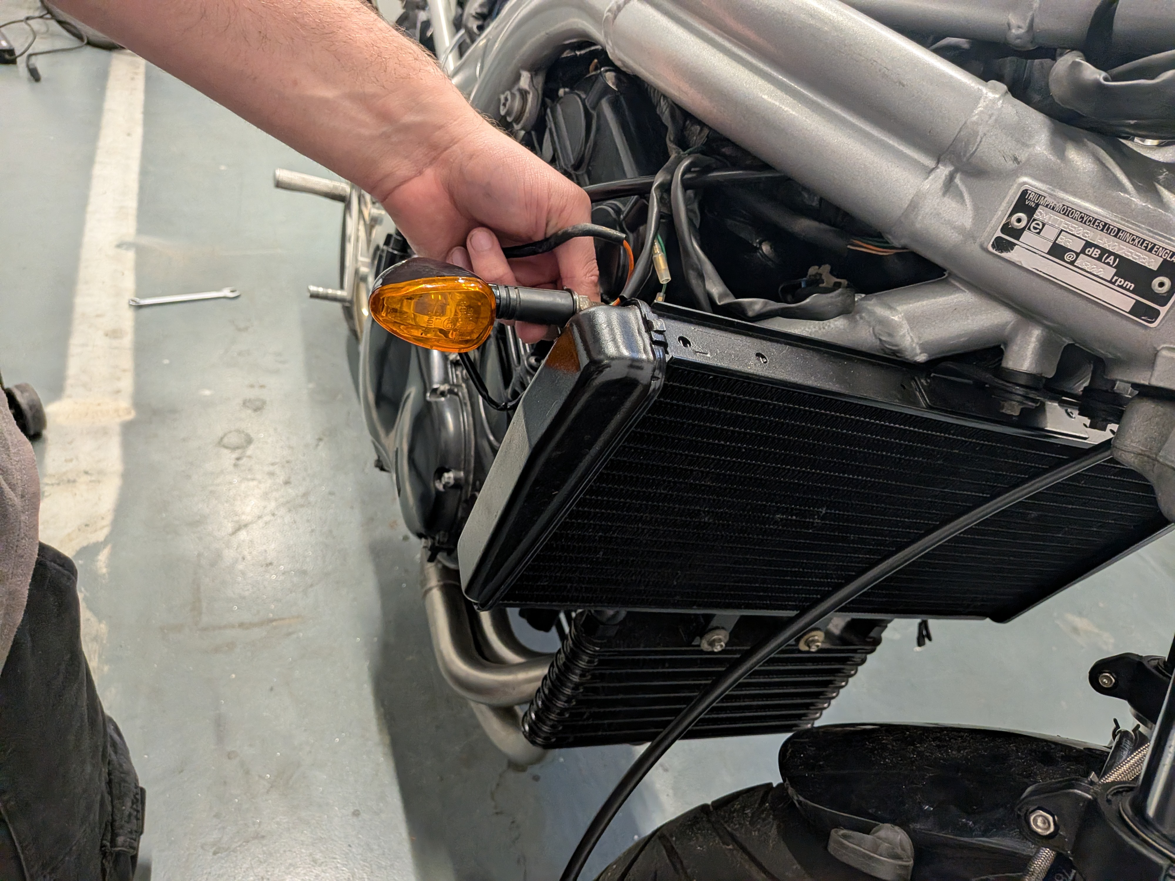
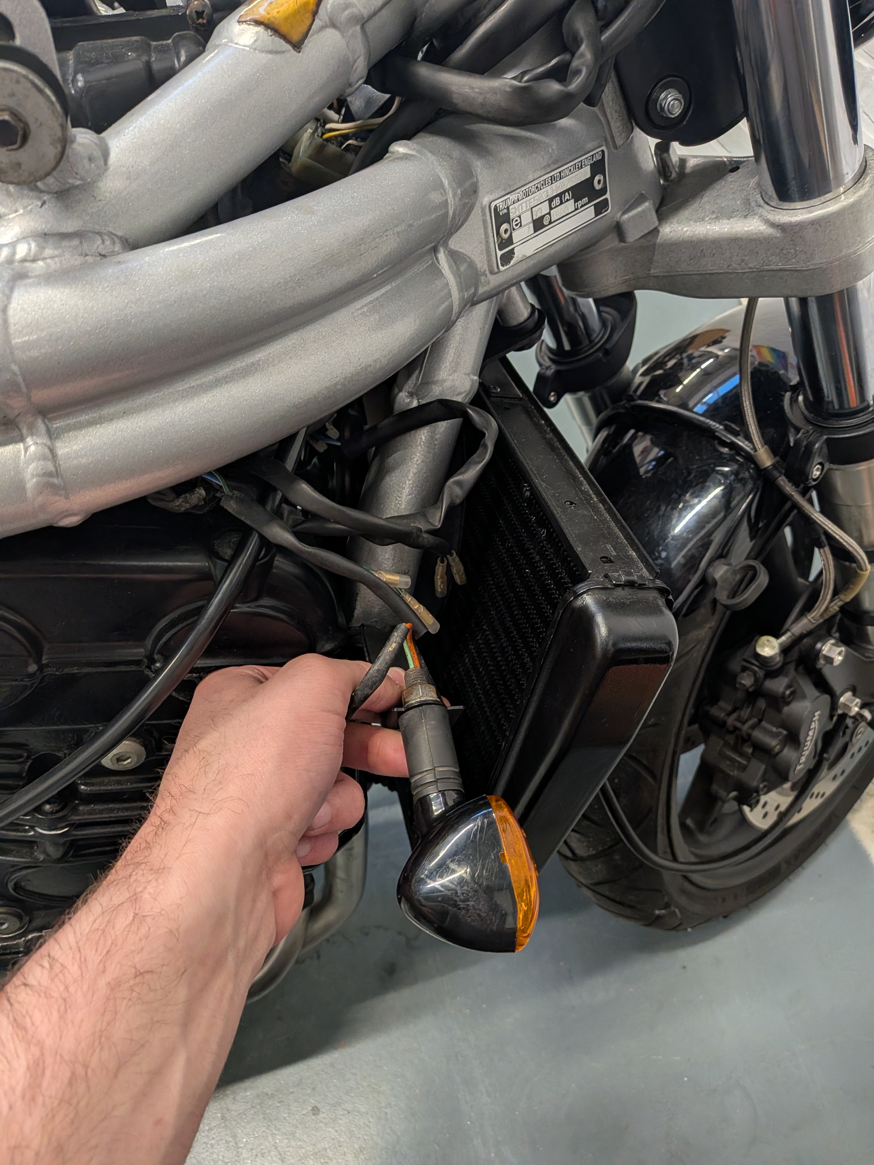
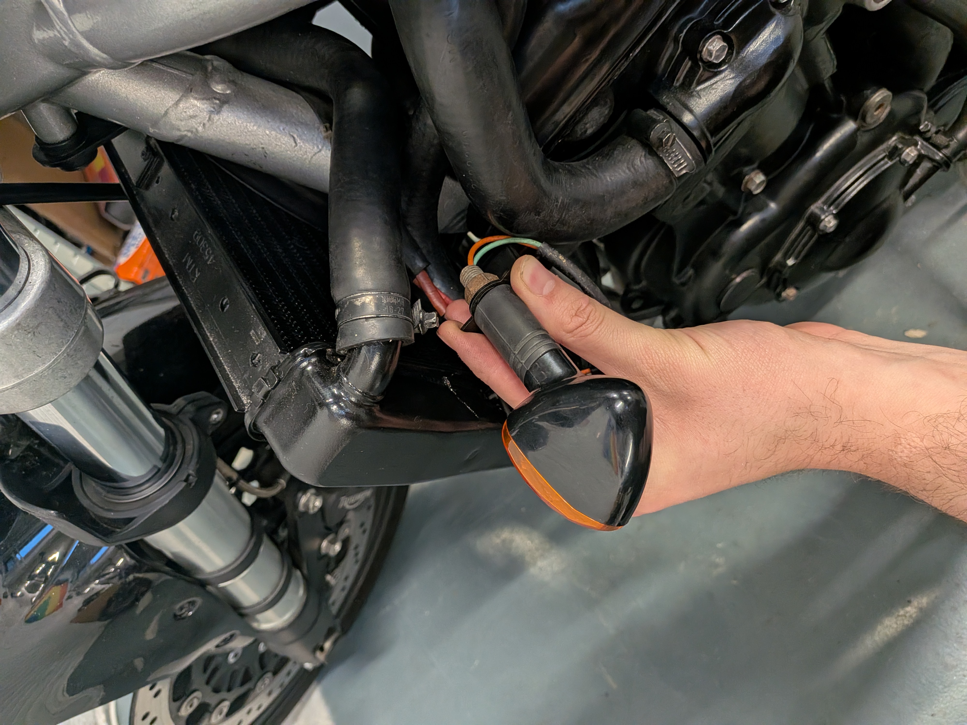
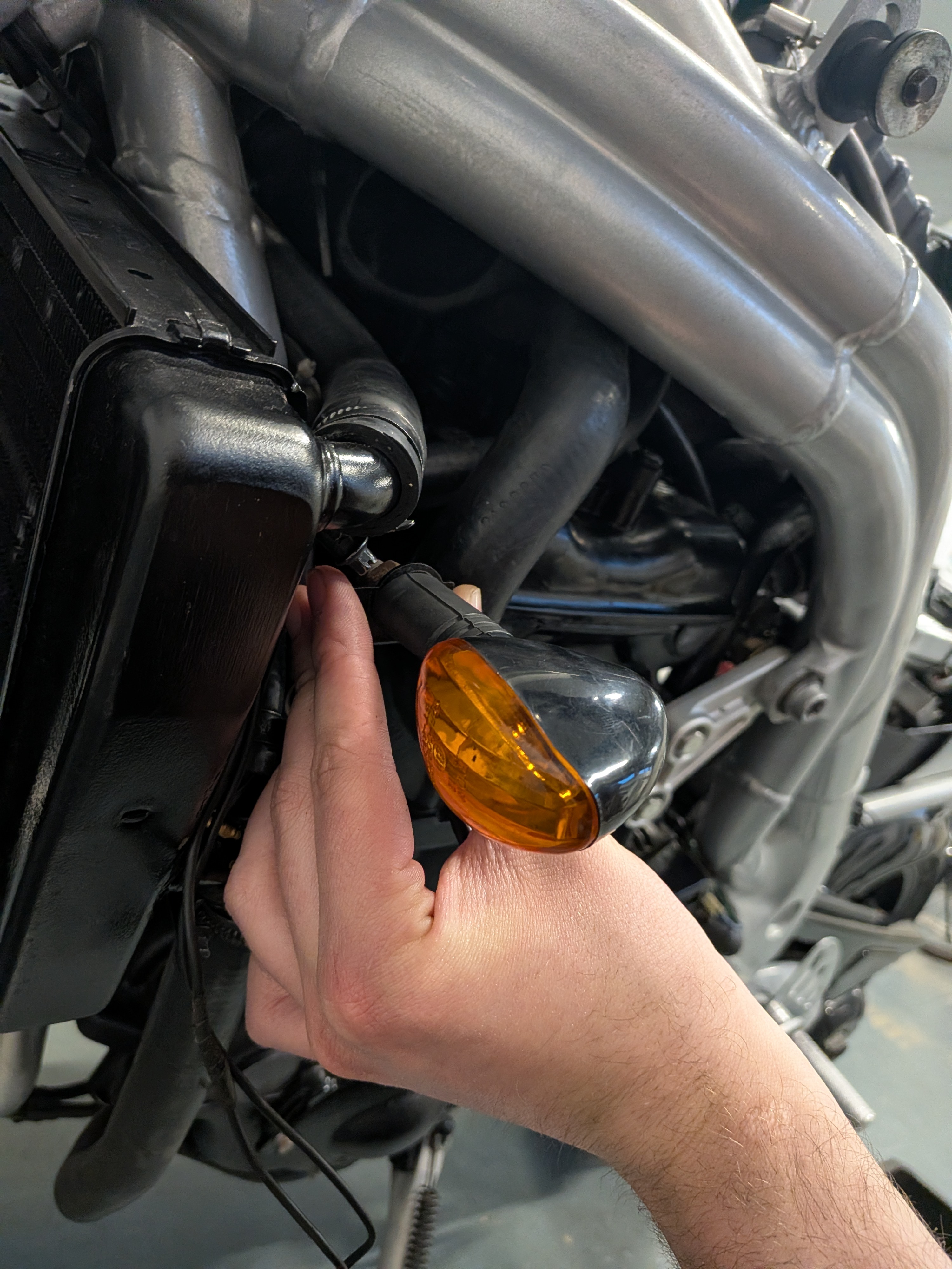
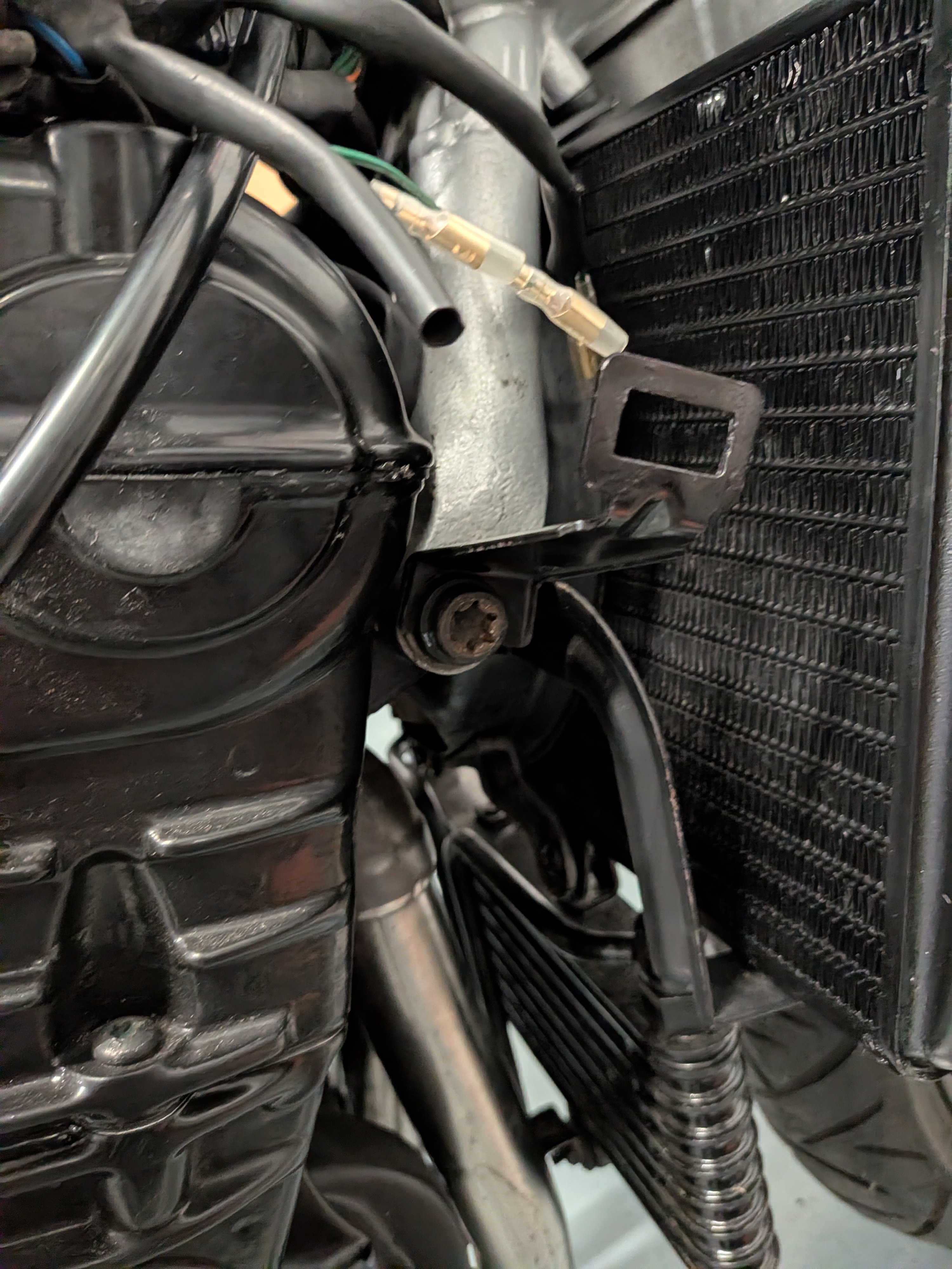
Right click or long press to view full-size image in a new tab
Horn
After having solved the indicators I figured I might be able to do the same for the horn.
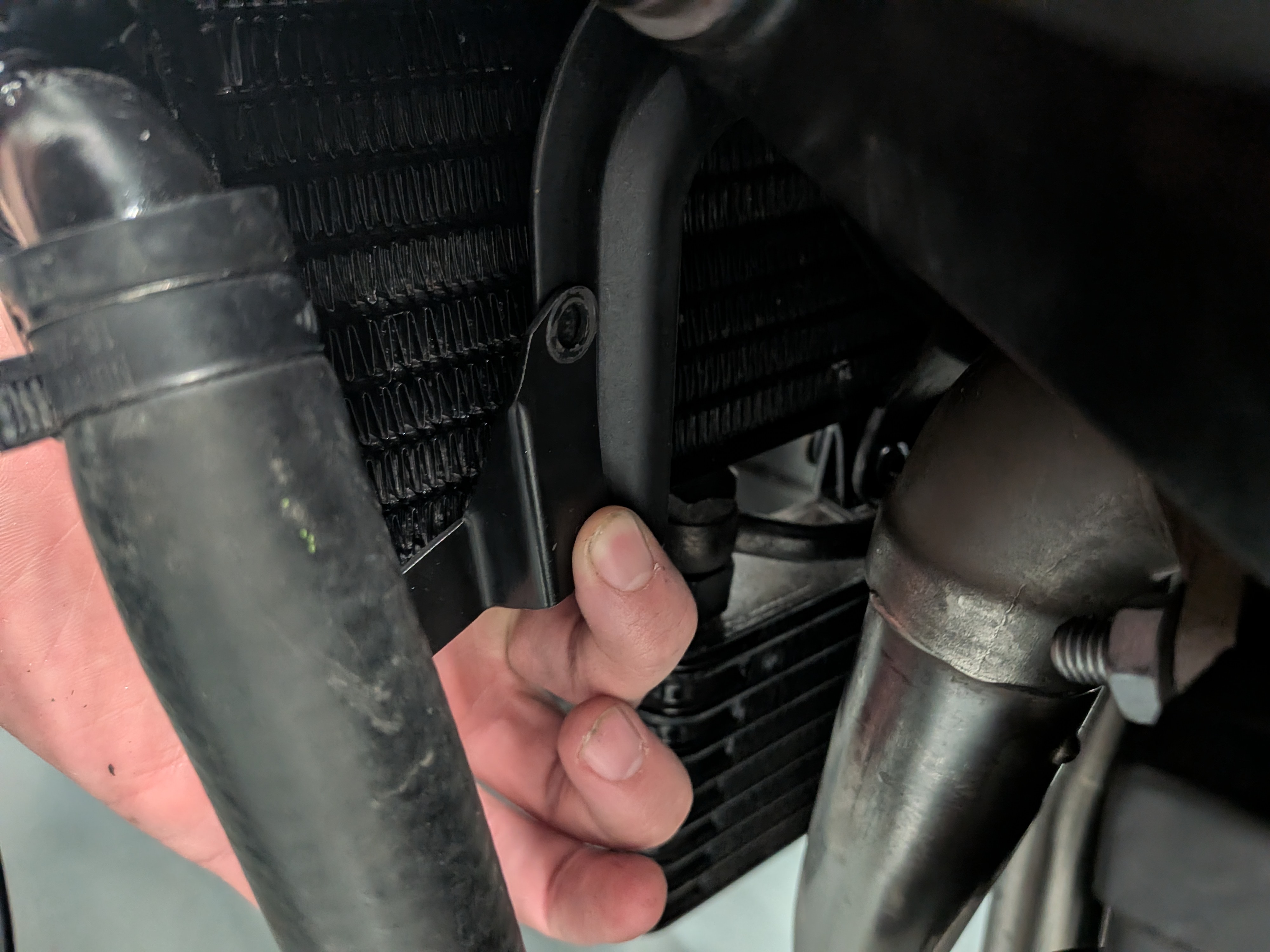
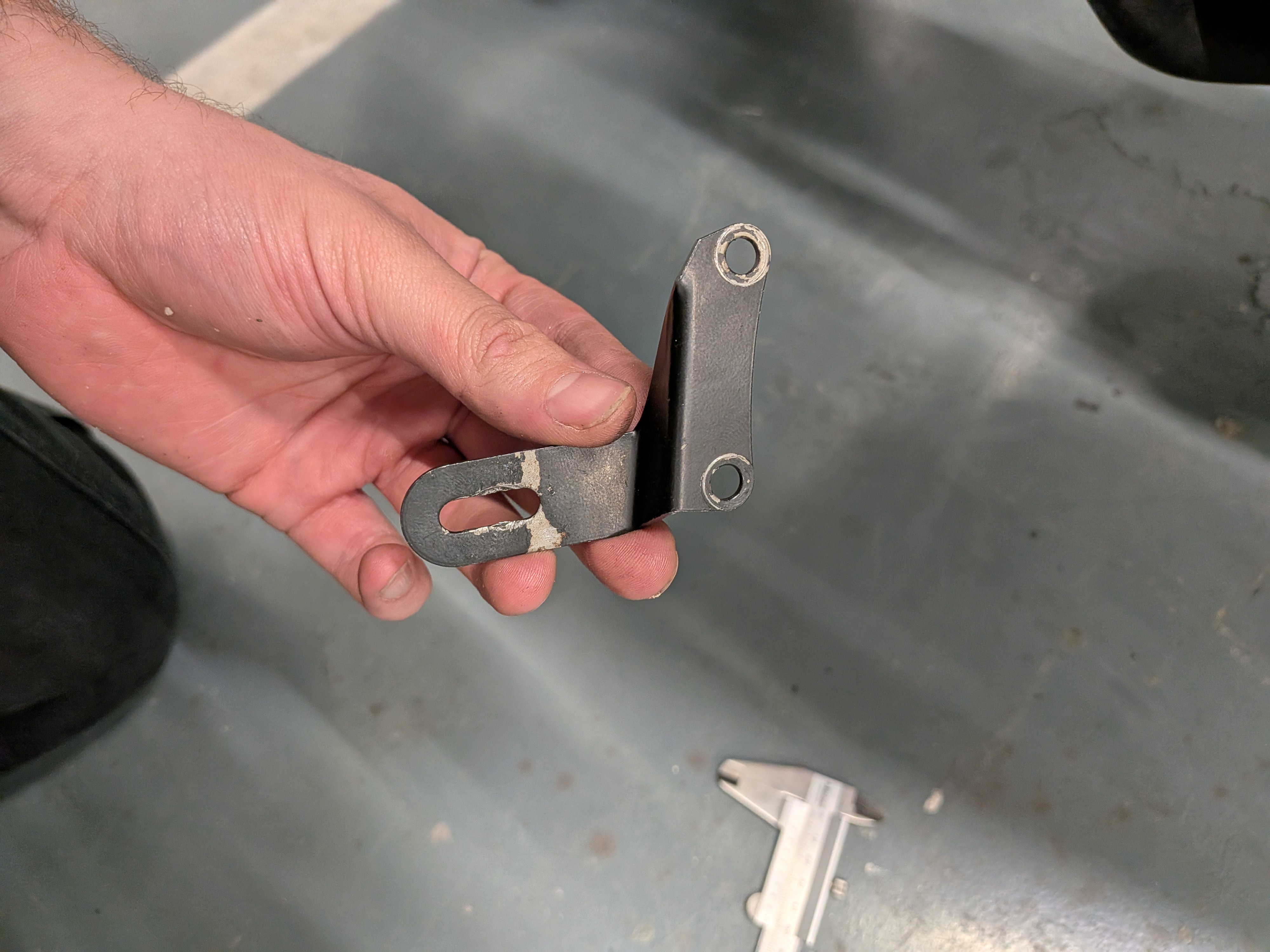
After a bit of puzzling I was able to make one of the left over fairingb brackets work as a horn mount. It fully clears and is attached to the radiator bracket.
This does require initially having to take off the radiator bracket, drilling 2 holes and bolting it all up.
But just like the indicators I think this is quite the elegant and clean solution!
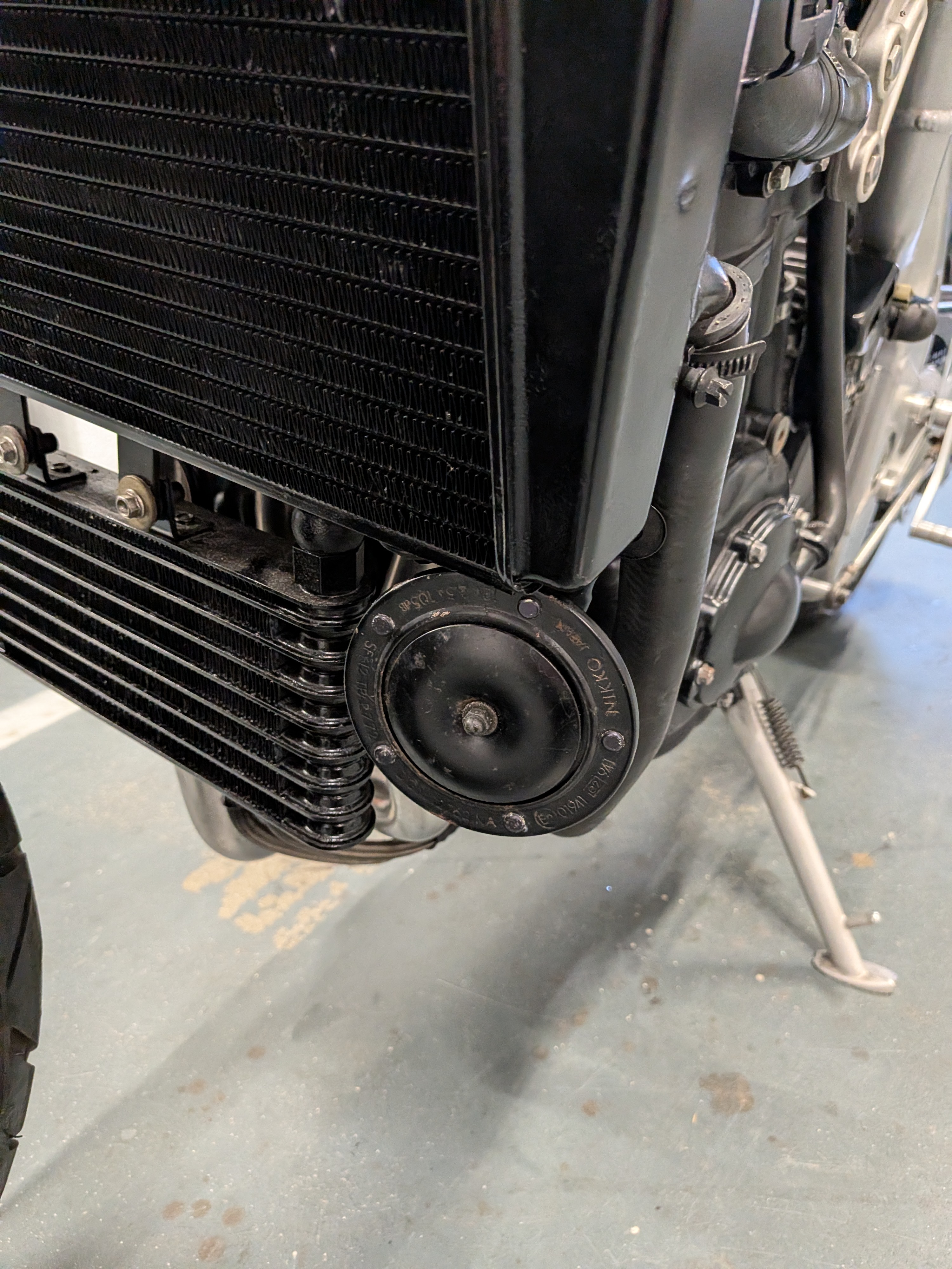
Additional photos of the horn.
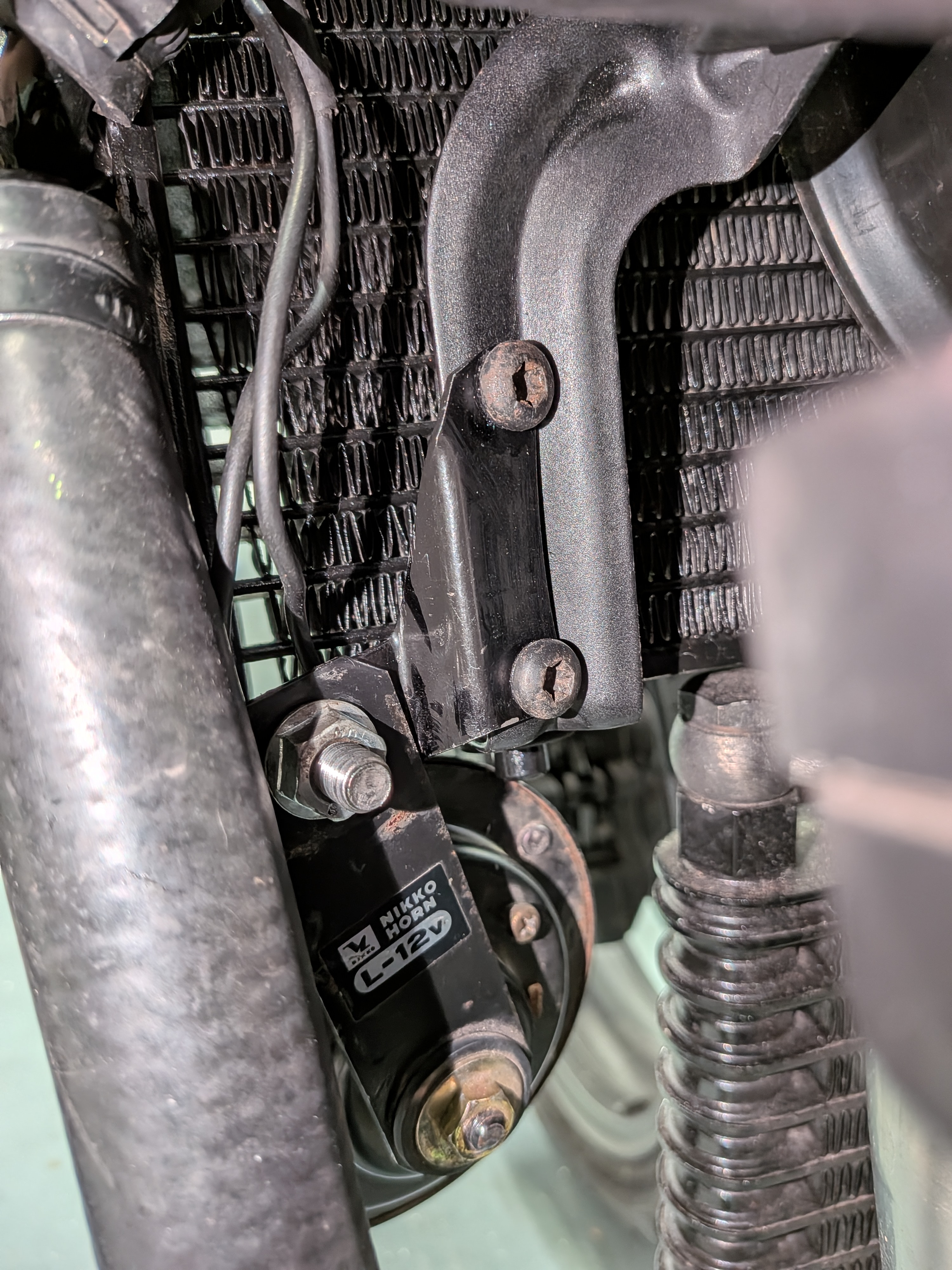
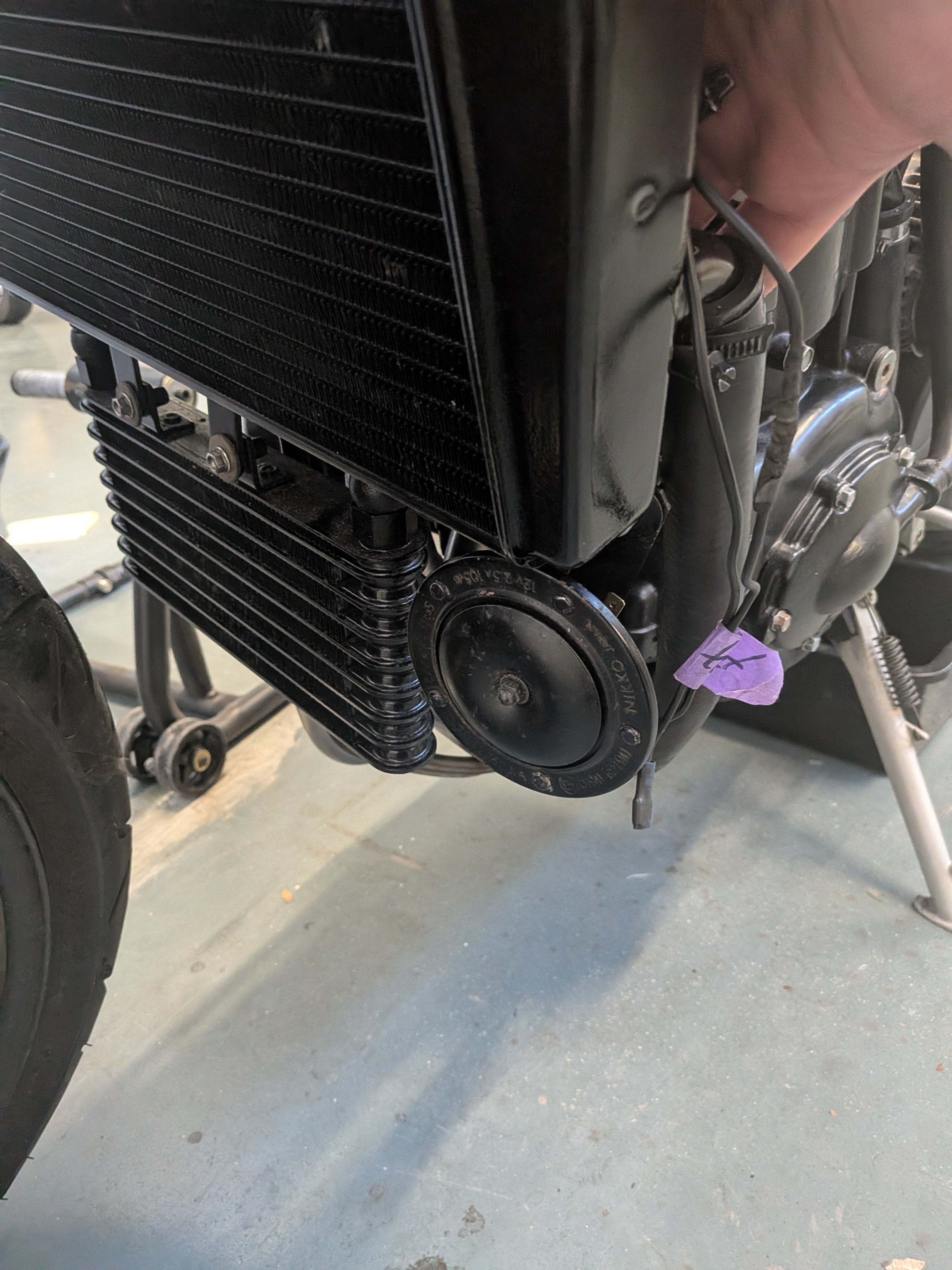
Right click or long press to view full-size image in a new tab
Mirrors
This wasn’t as much of a challenge, as I had a vision from the start.
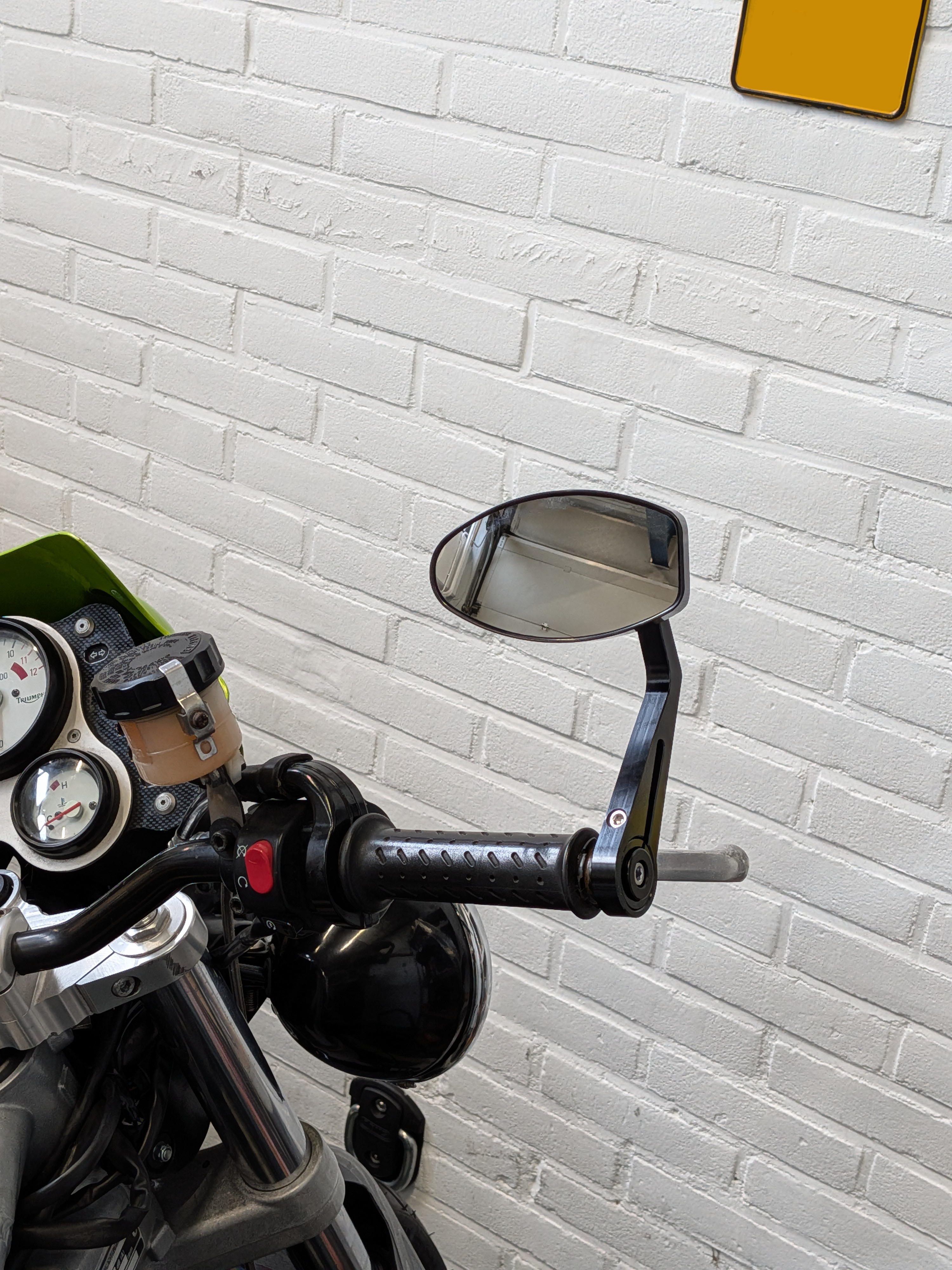
I ended up going with a set of CNC aluminium bar end mirrors. But as with all things in this project it wasn’t quite going to be that simple.
Upon trying to install the new kit it became quite obvious that the bar end weights it came with did not fit my bars, which have a standard ID of 18mm, where as the bar ends that came with the kit were 19mm. Nothing the CNC with a 4th axis attachment couldn’t fix!
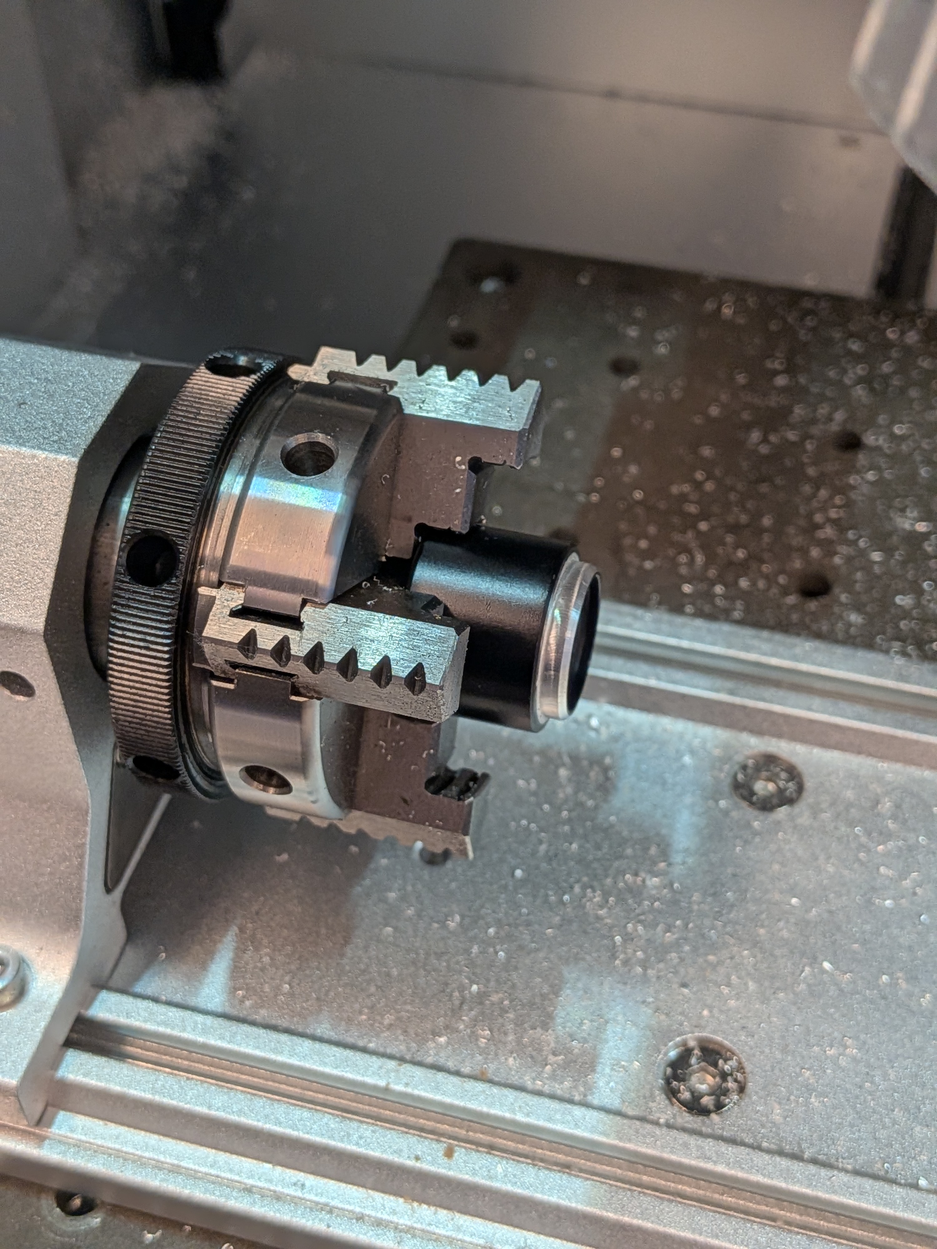
Additional photos of the mirrors and bar end weights.
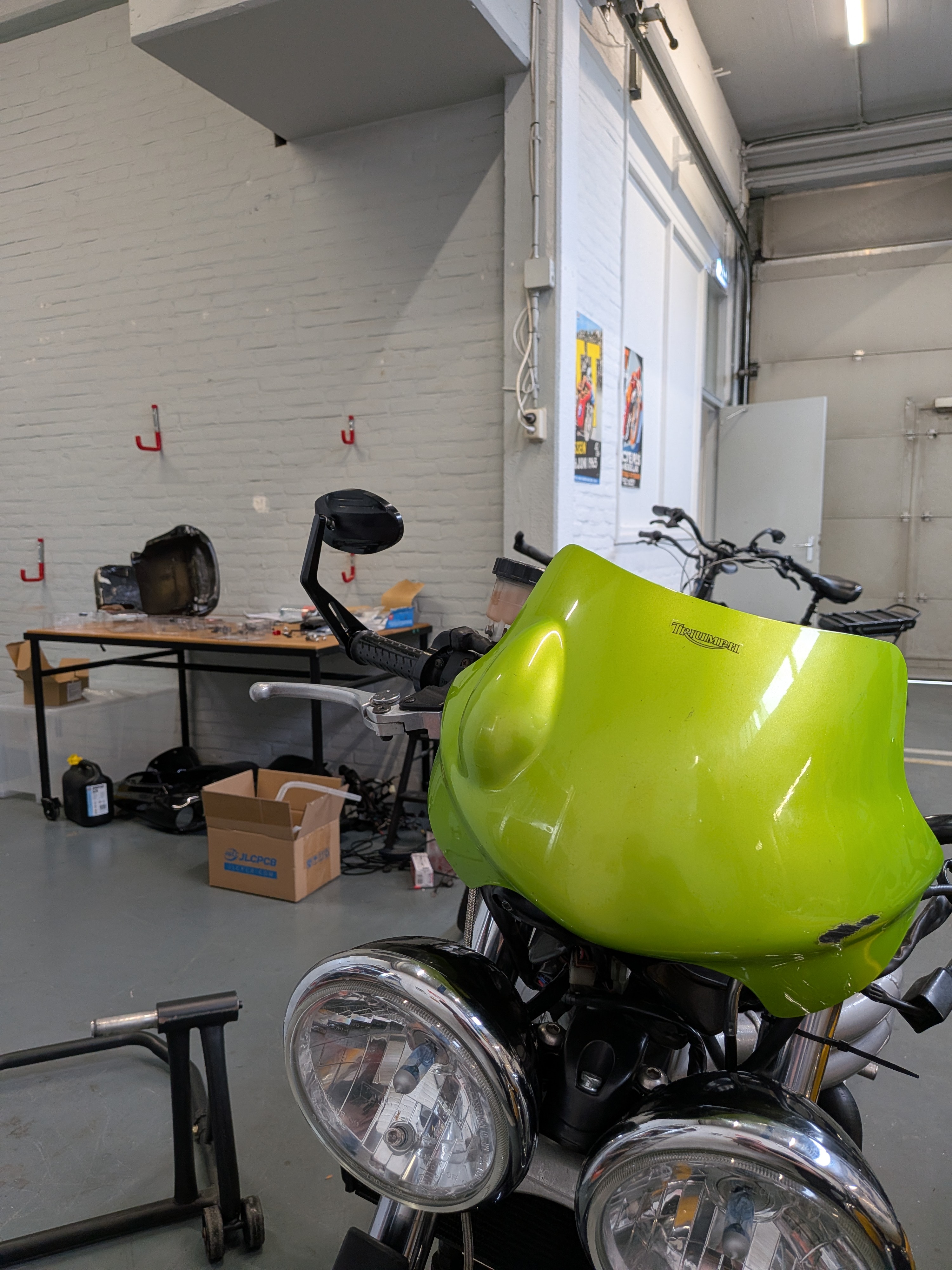
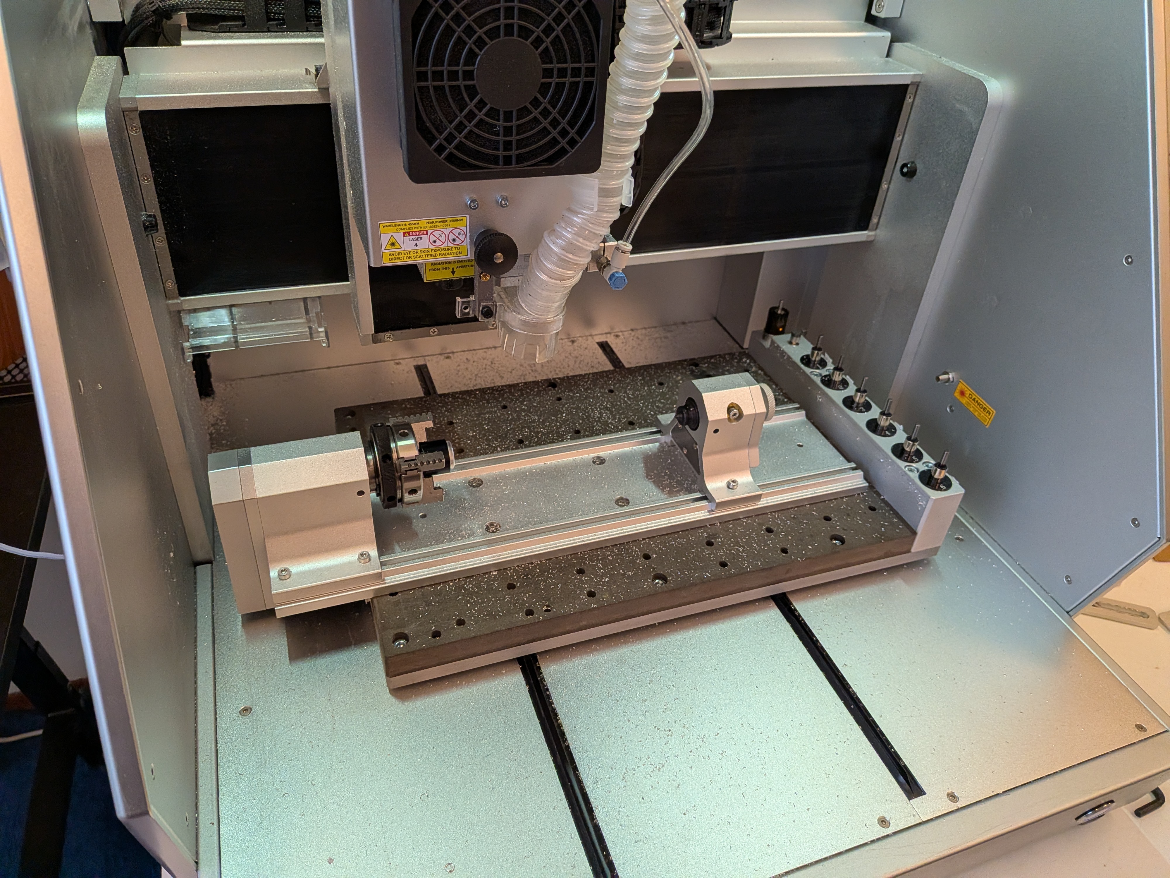
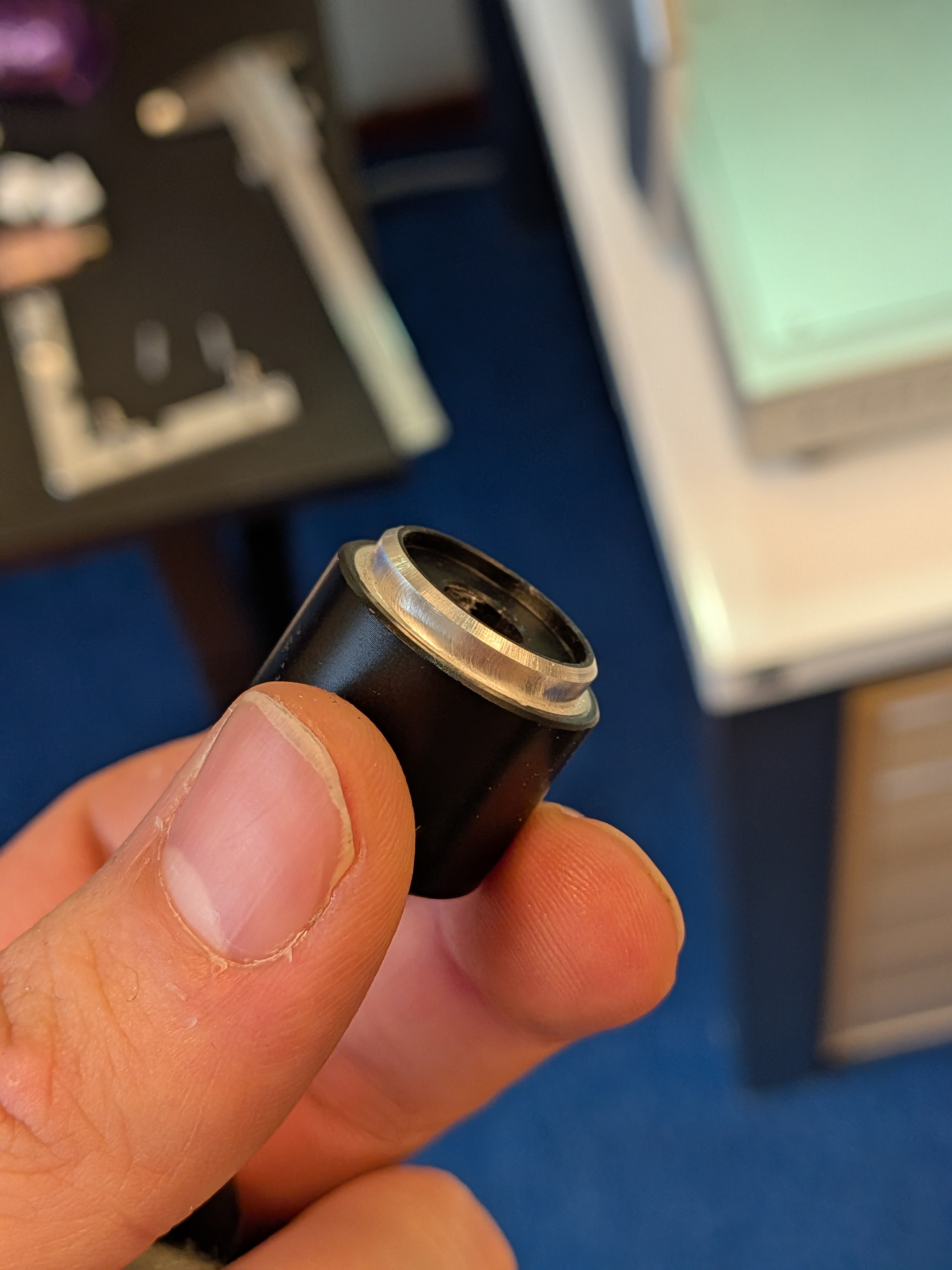
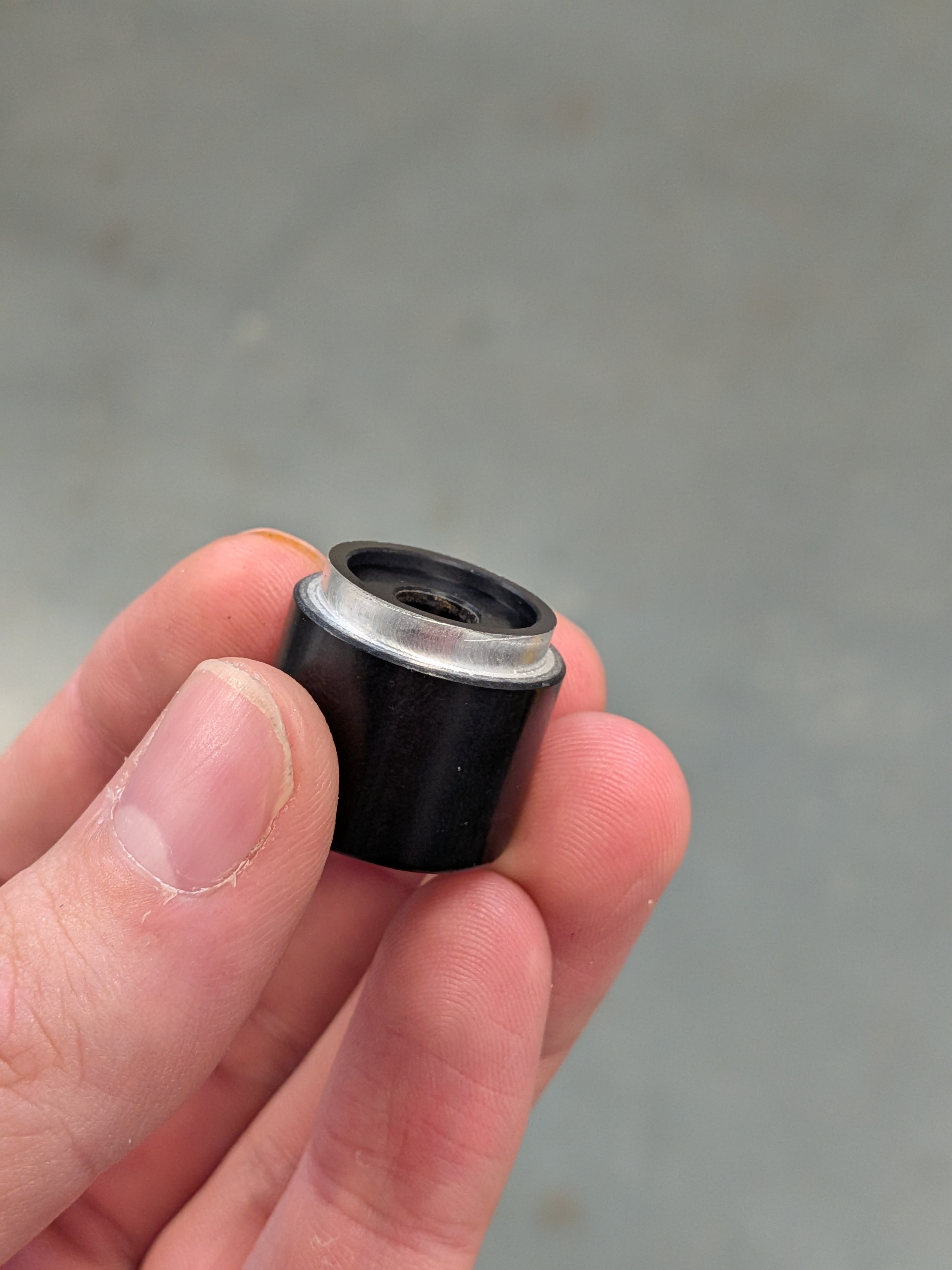
Right click or long press to view full-size image in a new tab
Broken Plastics
I feel like such a broken clock saying this, but these bikes all start to suffer from the same issues, one of which being the plastics.
At this point the plastics are 27 years old (as of the writing of this article in 2026) and aren’t getting any younger.
This means things are brittle, prone to cracking and crumbling. Sadly my bike was no strange to this either.
Luckily the fix is pretty simple and there are various ways of going about it such as: plastic welding with heat set staples, plastic welding by actually melting fresh plastic into it, glueing, fiberglas and epoxy or even chemically re-bonding and reinforcing the original plastics.
I opted for a combination of plastic welding and chemically reinforcing after. The welding speaks for itself, it’s where you melt metal staples into the original plastics to hold them together.
However I combined it with a method that adds fresh ABS plastic to the mix using acetone. Simply dissolve some fresh new ABS inside of acetone (tamiya plastic cement works well too) and let it dissolve.
Once you get a nice consistency resembling thick custard you can use a brush to apply it to the cracks and fill them up, or brush it on to for example the screw posts on the rear pillion cover.
The acetone in the mixture breaks down the ABS on a chemical level both the new and the old, which recrystalizes once the acetone evaporates, essentially chemically bonding them together. Whilst this doesn’t rejuvenate the old ABS it does bond the broken part back together with some fresh new ABS in the mix.
So instead of glueing you are literally chemically bonding it back toghether.
The results of this especially when building up a new shell around screw posts may not be the pretiest, but it works well. And for exterior visible parts you can just sand them back down/smooth.
I’m still in the process of doing this, so I’ll add some pictures later when done.
Coolant
When I got the bike and giving it a good once over it became apparent that the system had little to no coolant in it, but the overflow reservoir was filled way past the max line. despite the previous owner mentioning it was topped up.
I decided this was a great time to just flush the system and fill it all back up with fresh coolant. This all went without any significant troubles.
Replaced all the copper washers, flushed the system a few times with distilled water before finally filling it back up with Putoline NF (green).
I got all the air out of the system and all seemed well, until I noticed a small puddle under the bike. After some investigating I found this:
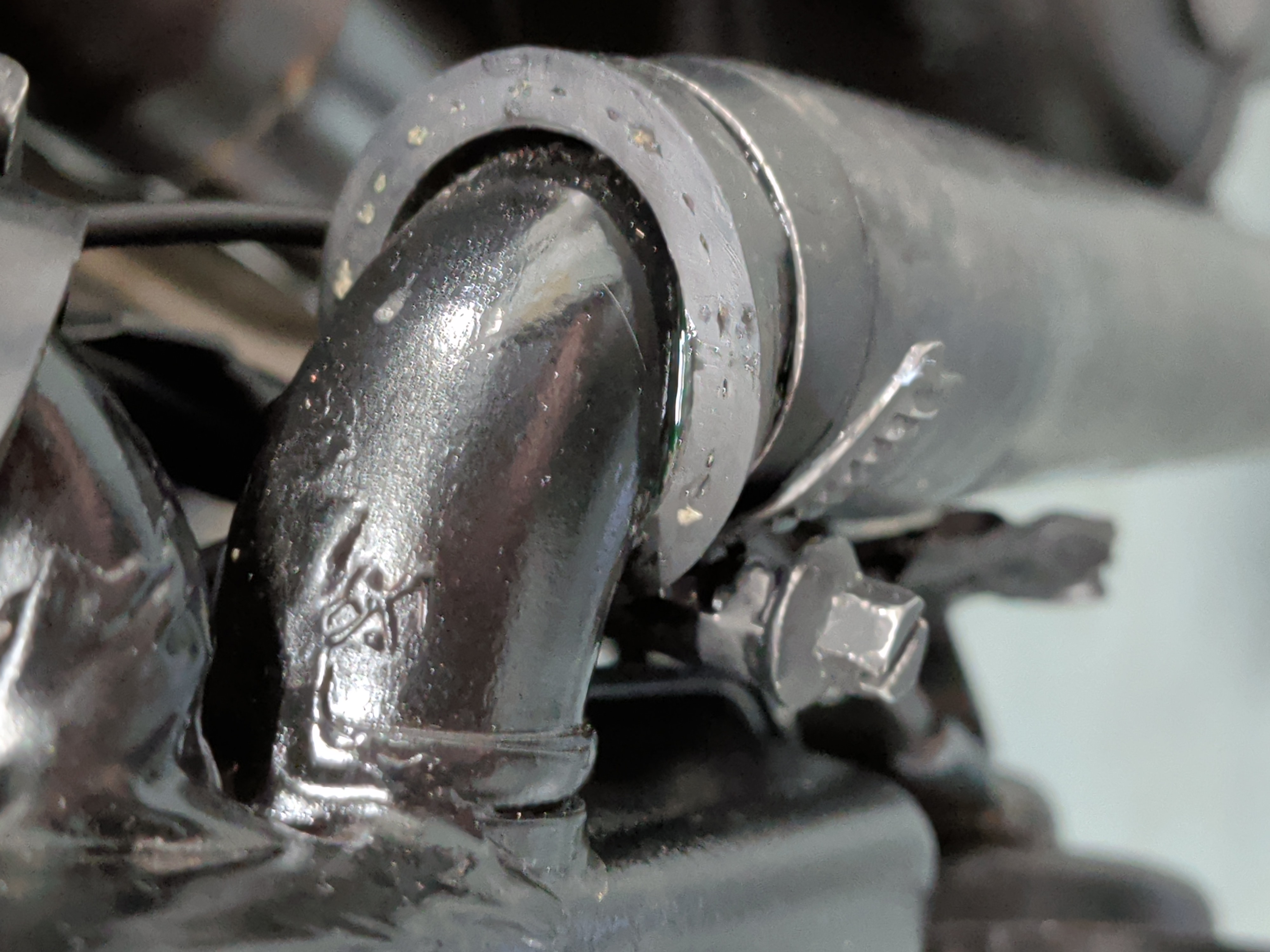
The hose was slid onto the radiator too far causing the clamp to not seal properly which caused a small leak.
After adjusting the hose and tightening the clamp that seemed fixed, until the bike got warm, suddenly there were even more drips.
Turns out every single hose clamp was barely hand tight, none of them were actually clamping on the hoses properly. Luckily that’s an easy fix and the bike was without leaks shortly there after.
I do plan to fully replace all the hoses and clamps at some point in the future though, as they are aging, no cracks as of yet and they do still feel supple for now.
I ended up using Putoline NF Cooland.
Exhaust
When the previous owner got the bike it came with an akrapovic system installed. However by the time I got it she was equipped with the TOR high up exhaust.
But as you may have noticed that one is no longer on the bike, instead the bike is now fitted with the original OEM silver can that it once came with from factory.
I do have good reasoning for the change though, the main one being noise levels, I live in a big very densely populated city where it feels like cops are around quite literally every corner. Whilst I have not been pulled over just yet I do just want to be able to enjoy my bike without worrying about the legality of my exhaust.
What was a nice bonus though is that the headers, studs and exhaust nuts were all replaced and are absolutely brand spanking new! Saves me the pain from having to deal with rusted seized exhaust studs in the future!
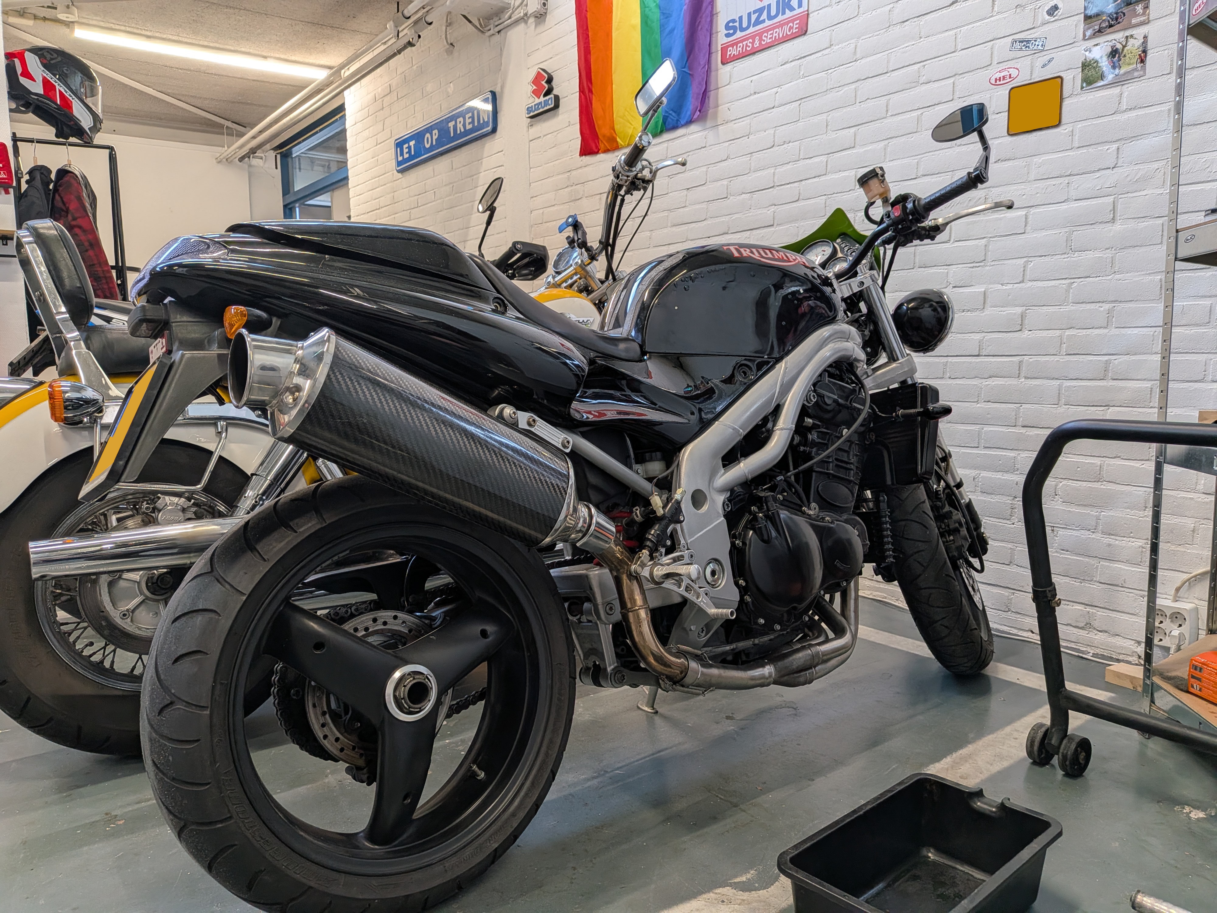
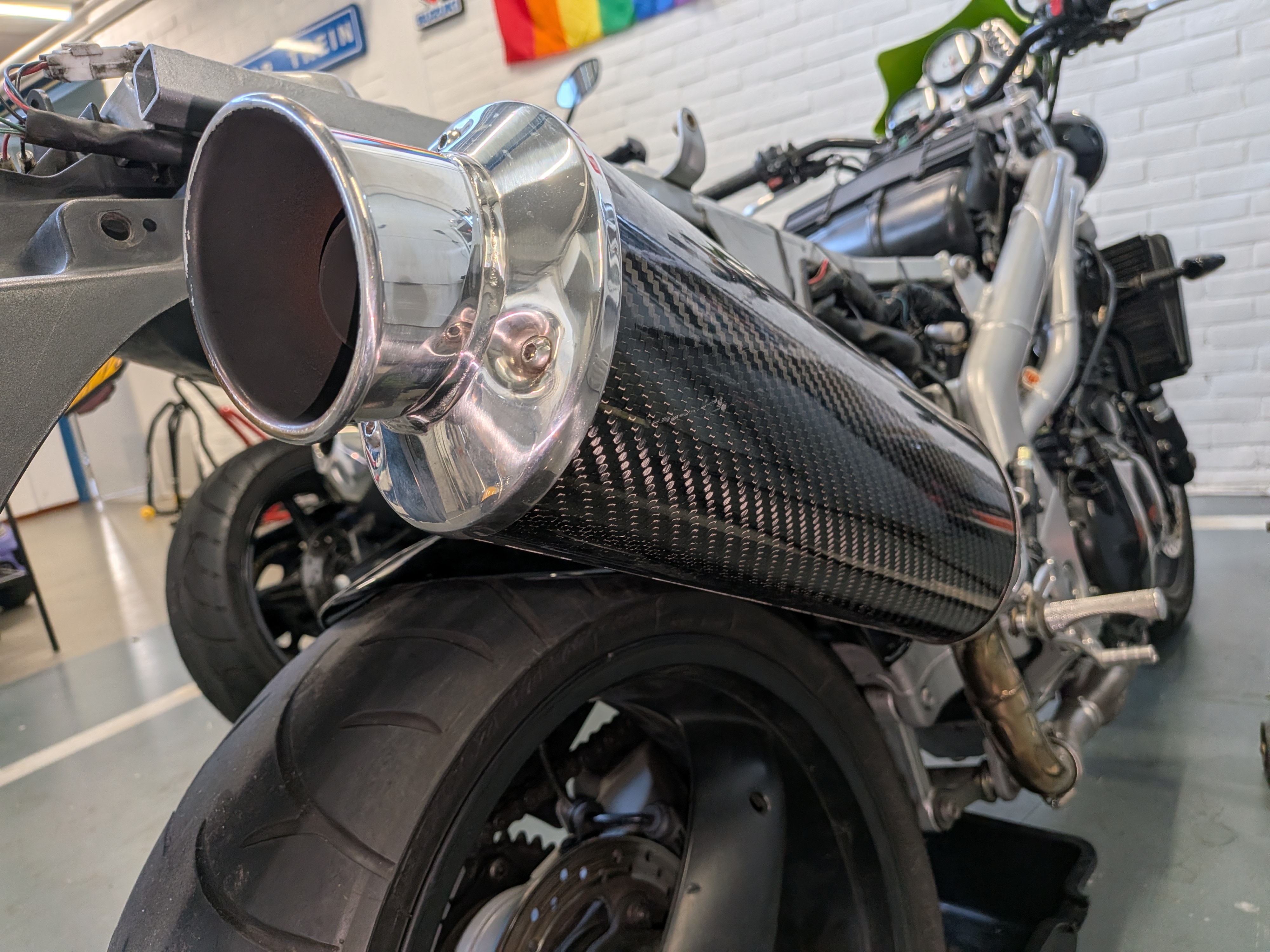
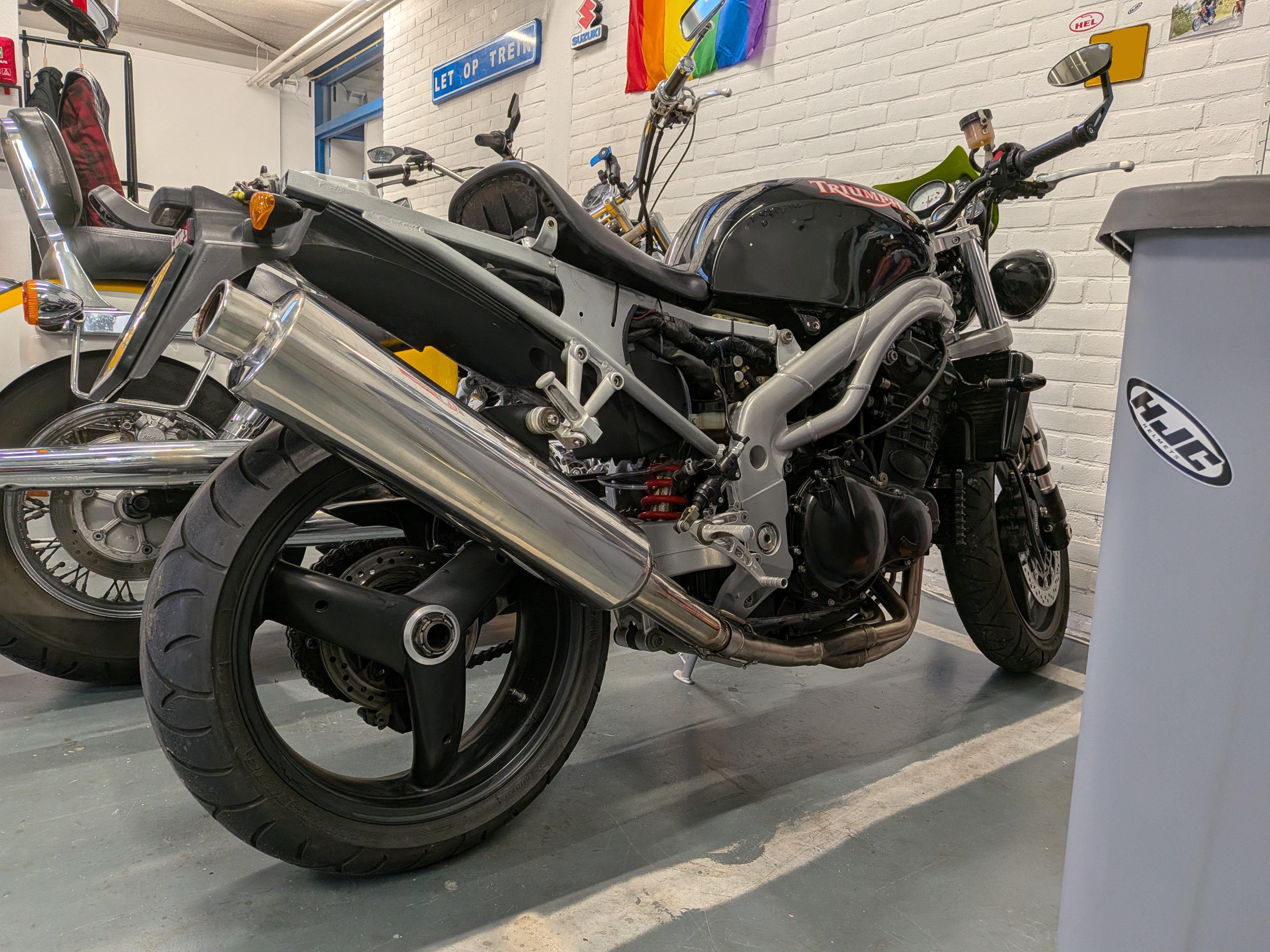
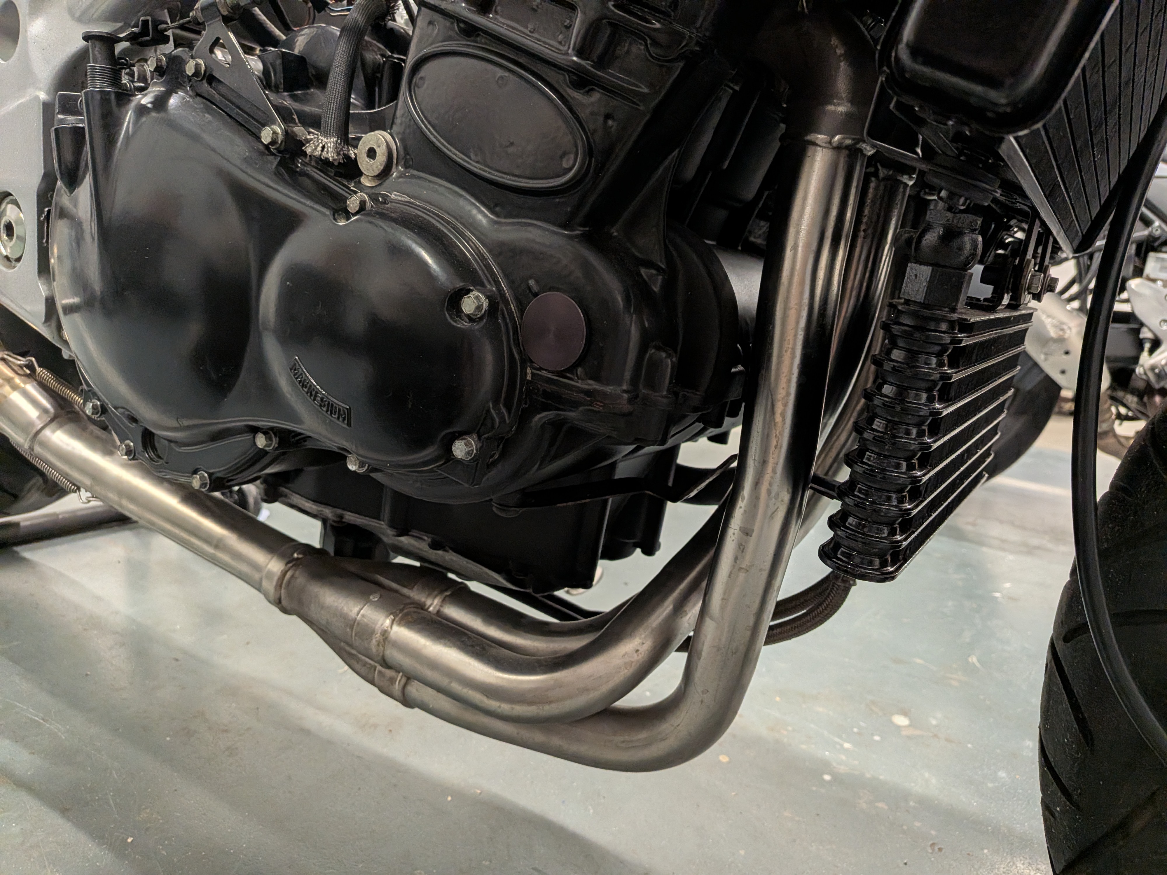
Right click or long press to view full-size image in a new tab
Brake Sensor
Rear brake didn’t seem to cause the brake light to come on, long story short the cable had snapped off on the brake pressure sensor. I used a generic replacement that was M10x1.25 from TRW with standard 10mm aluminium sealing rings. Works a charm, no leaks.
Clutch Cable
The clutch cable that came on the bike was the original one from the Daytona, however due to no longer having clip-on handlebars it was making all kinds of weird twists. This resulted in a nearly impossibly hard to pull clutch. I ended up using a Speed triple 1050 clutch cable which is easy to route and makes for a wonderfully soft clutch pull. You can find a good forum post about it here. However I routed the cable slightly differently but it’s almost identical.
Battery And Tray
The bike came without a battery, so after some research I found the correct battery to be the Yuasa YB14L-A2.
However upon installing it I found it sitting way too high!
This could obviously cause issues, which is when I learned that the daytona could also have come with a slightly smaller battery, for which it uses a battery tray with a raised section.
Finding a new battery tray proved difficult, so I did the cheapest and fastest option: cut the platform off, which is what left me with:
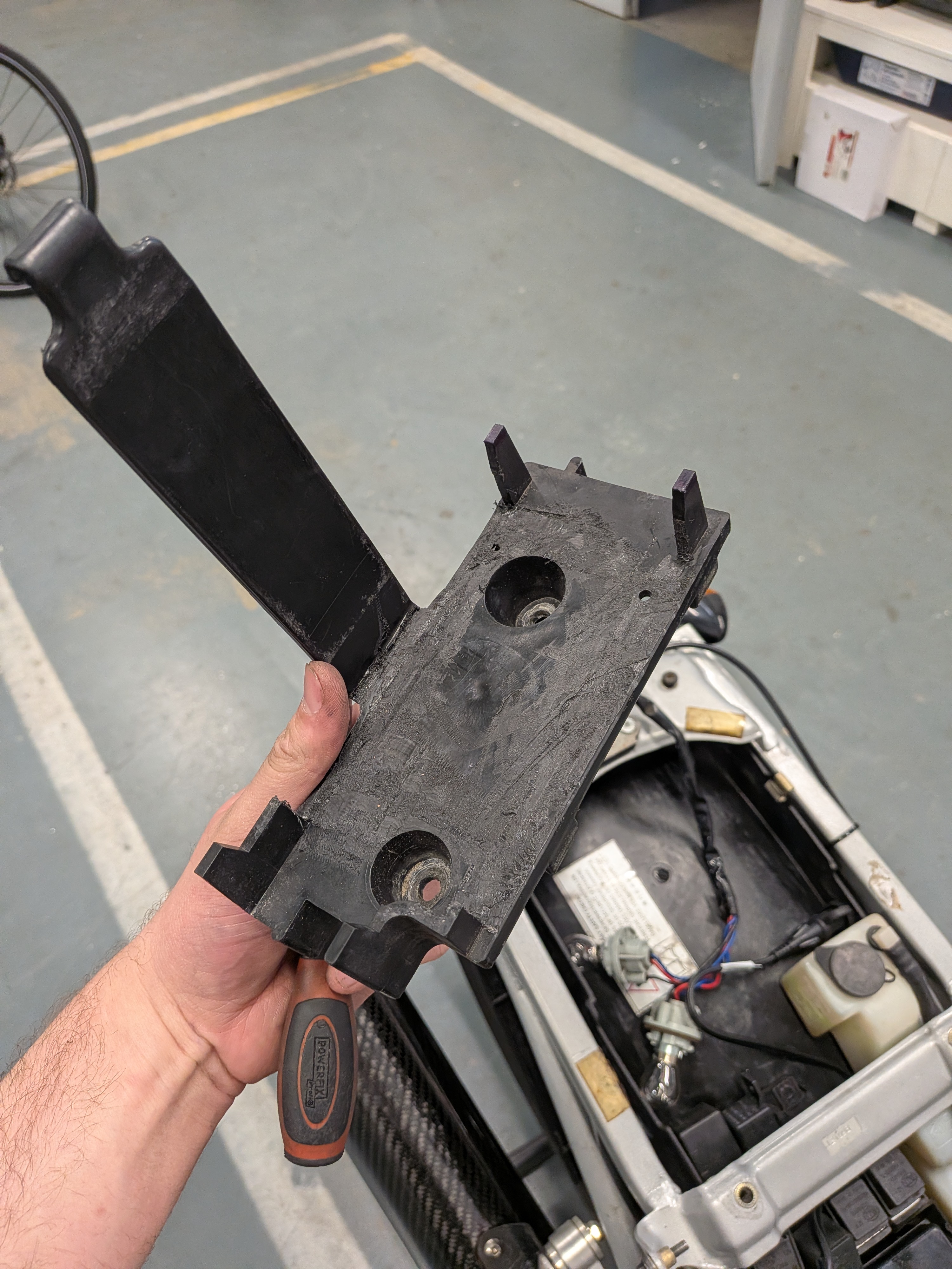
To cut the tray I just used an oscilating multitool.
Here’s the battery before and after:
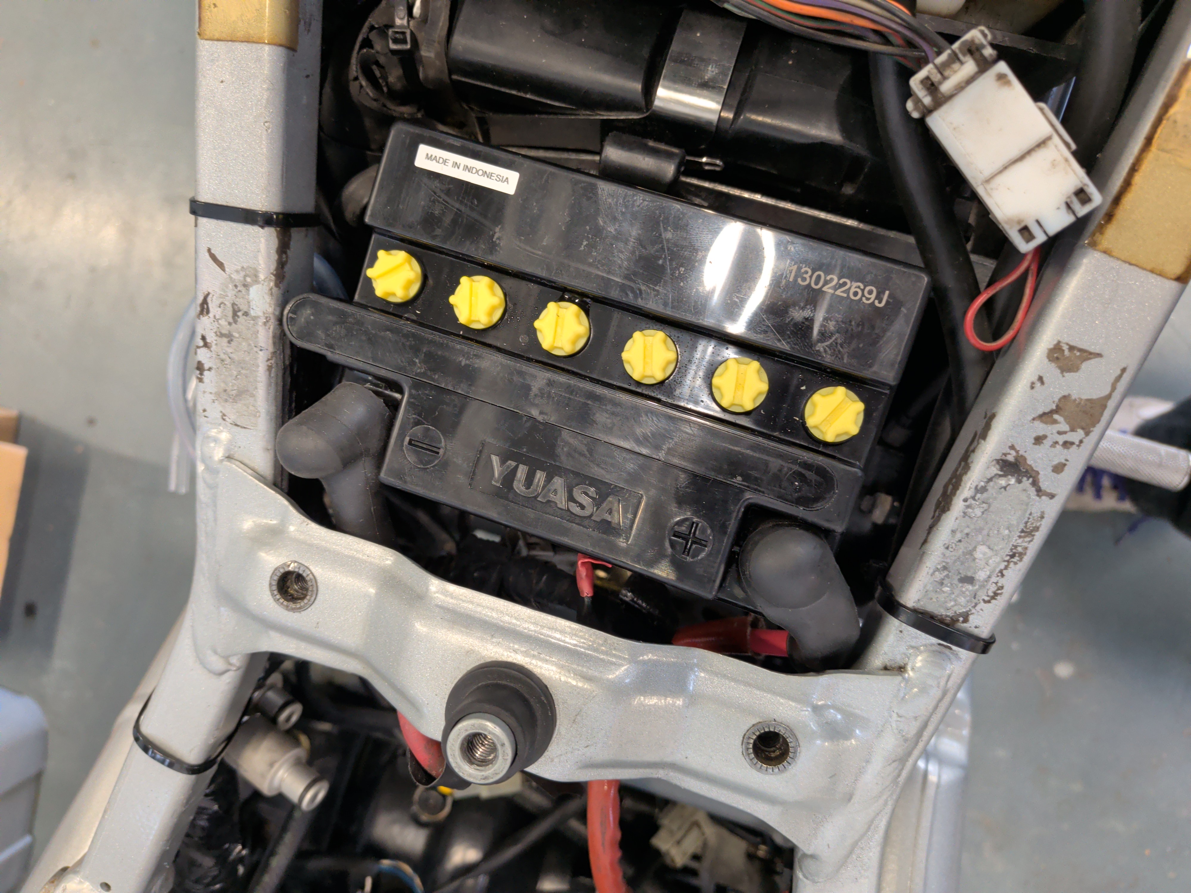
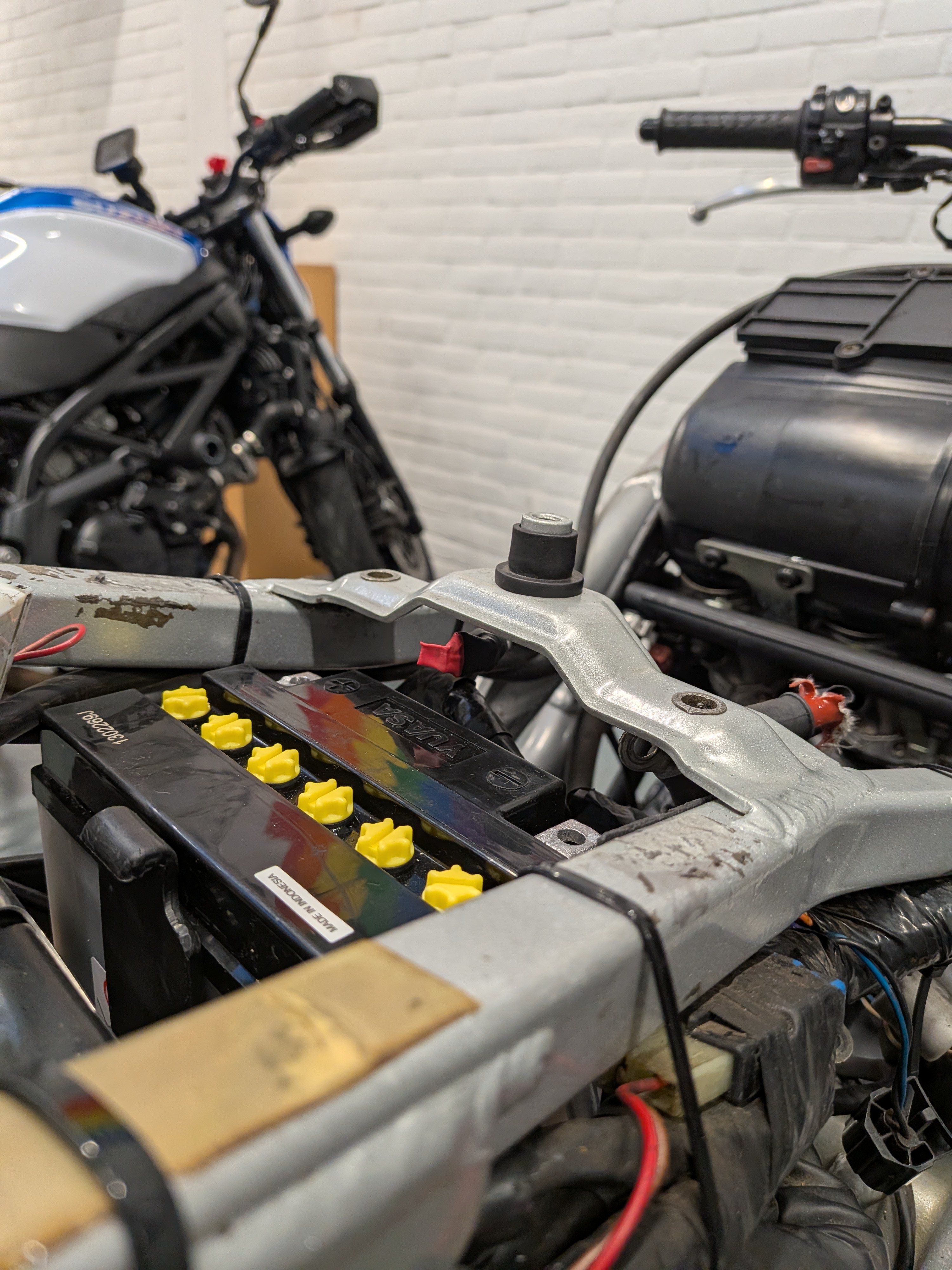
It goes from borderline touching the frame to being nice and low again.
Wiring Shennanigans
Sadly the bike wasn’t a stranger to some peculiar wiring gremlins either…
Firstly the previous owner had swapped the full wiring harness and ECU (to my knowledge), but did include the other wiring harness.
On the new wiring harness I found that both the positive and negative terminal for the battery were red, so that was… interesting.
turns out the previous owner had extended the wire for some reason (it was properly done at least).
But the biggest issue by far has to have been the fact that he plugged the water temp and air temp sensor in backwards (they both have the exact same identical connector and the wires reach just far enough to be able to mess it up), but more on that later
IACV
As like literally every single triumph from this era mine also suffered from leaky IACV vacuum hoses despite not being the original ones. I have replaced them with proper silicone vacuum hoses which turned out nicely.
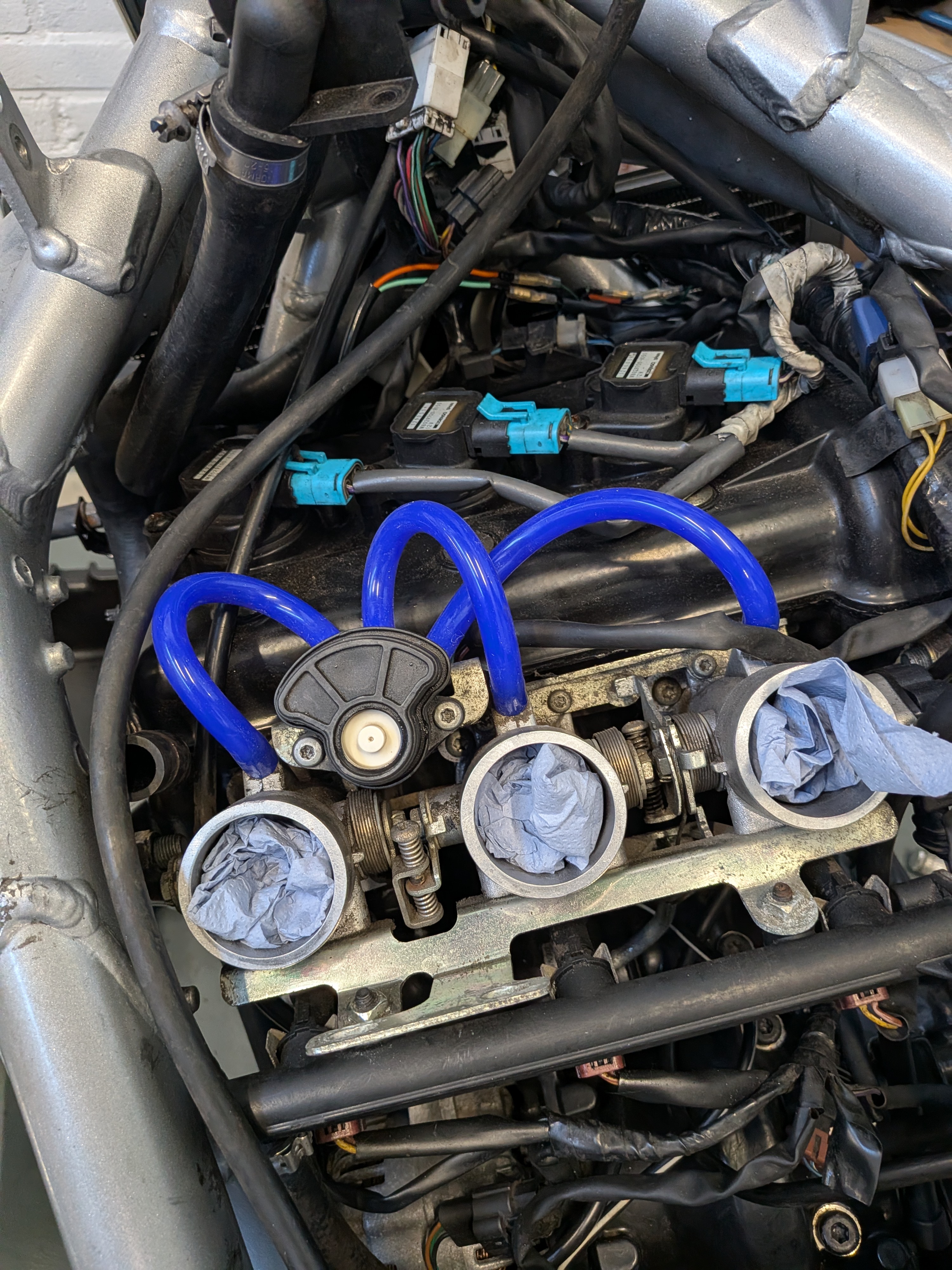
whilst I was at it I also cleaned out the IACV system.
Idle Issues
This issue really had me stumped for a while. To put it into perspective and list out the exact behavior I was observing:
- Cold starts are perfect
- IACV operation is correct
- Idle is fine for the first 30 seconds and gradually goes up
- Cooling fan doesn’t come on
- Bike rides fine and feels fantastic to ride
- Warm starts are rough/hard to start
- When stopping the engine and restarting it the idle is low and like clockwork raises to exactly 3000rpm each time.
- There are no airleaks
- Engine light is on
Here is a quick video showing the exact issue happening after restarting the engine when warm:
This really had me scratching my head for a while as nothing made sense and I couldn’t explain why it was behaving so weird yet predictable.
Given it had the engine warning light on I assumed the bike was unhappy about something…
I ended up ordering a specialized OBD adapter from here and used it along with TuneECU.
After hooking it up, clearing codes and running it until it got up to operating temperature the problem was staring at me quite clearly.
(aside from the coolant literally boiling out past an untightened hose clamp).
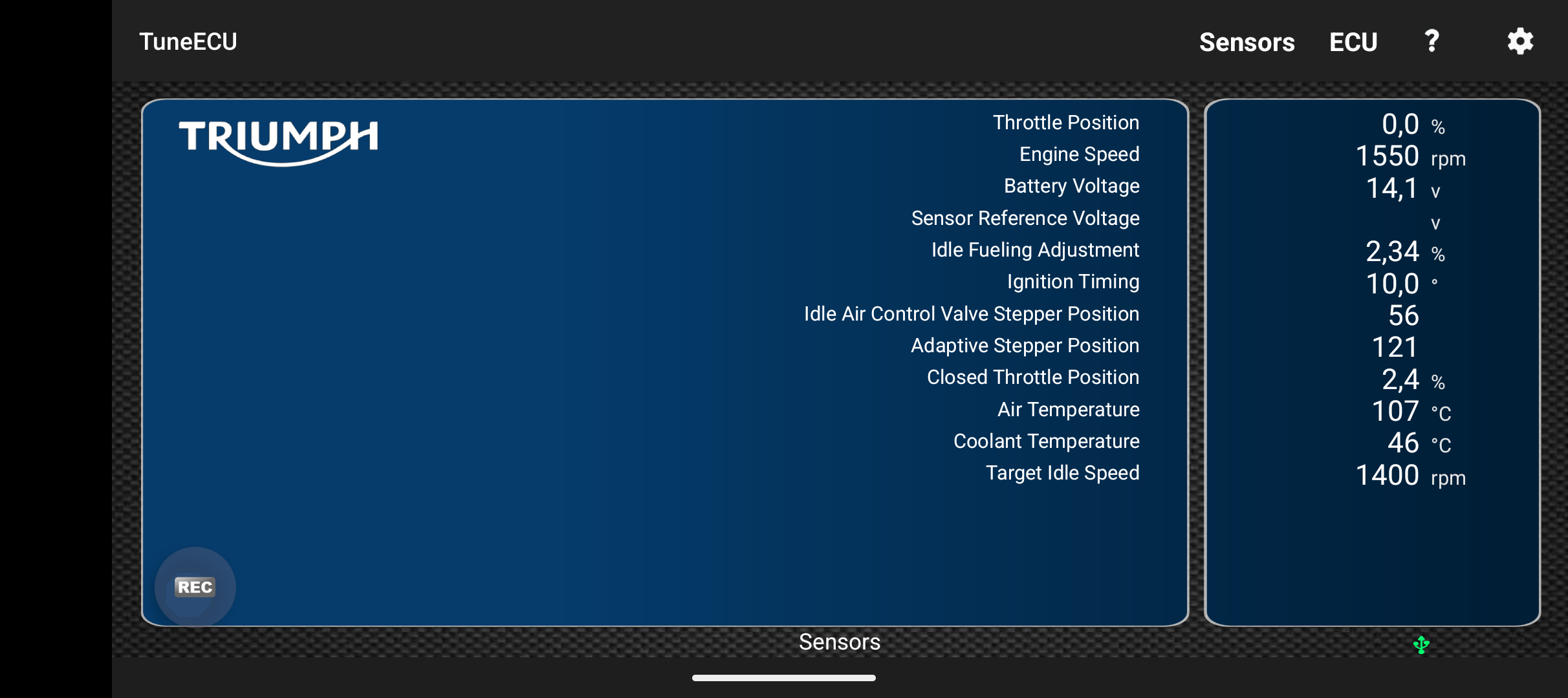
- Air Temperature 107c
- Coolant temperature 46c
Now… it doesn’t take a genius to see how that isn’t quite right, but if that wasn’t clear enough of a sign already, the bike also threw an error code for good measure.
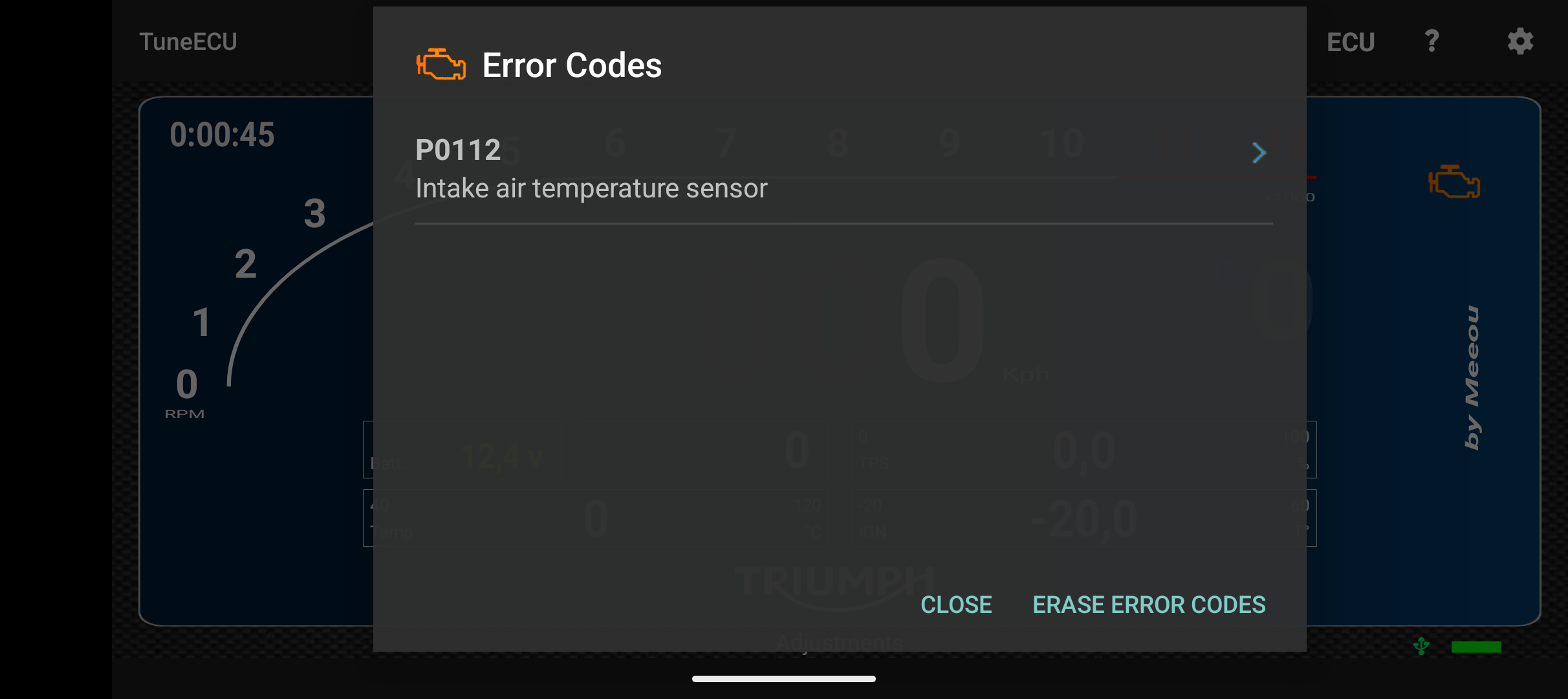
So I went investigating and found out that both sensor use the exact same connectors, and the wiring loom is long enough to quite easily allow them to be plugged in backwards.
And it turns out, to probably noones surprise: they were mixed up, I even checked the wiring diagrams just to make sure.
I spent a little time changing them around after which I cleared the engine codes and tried again, and what do you know it’s fixed!
The bike runs perfectly and is happy as ever!
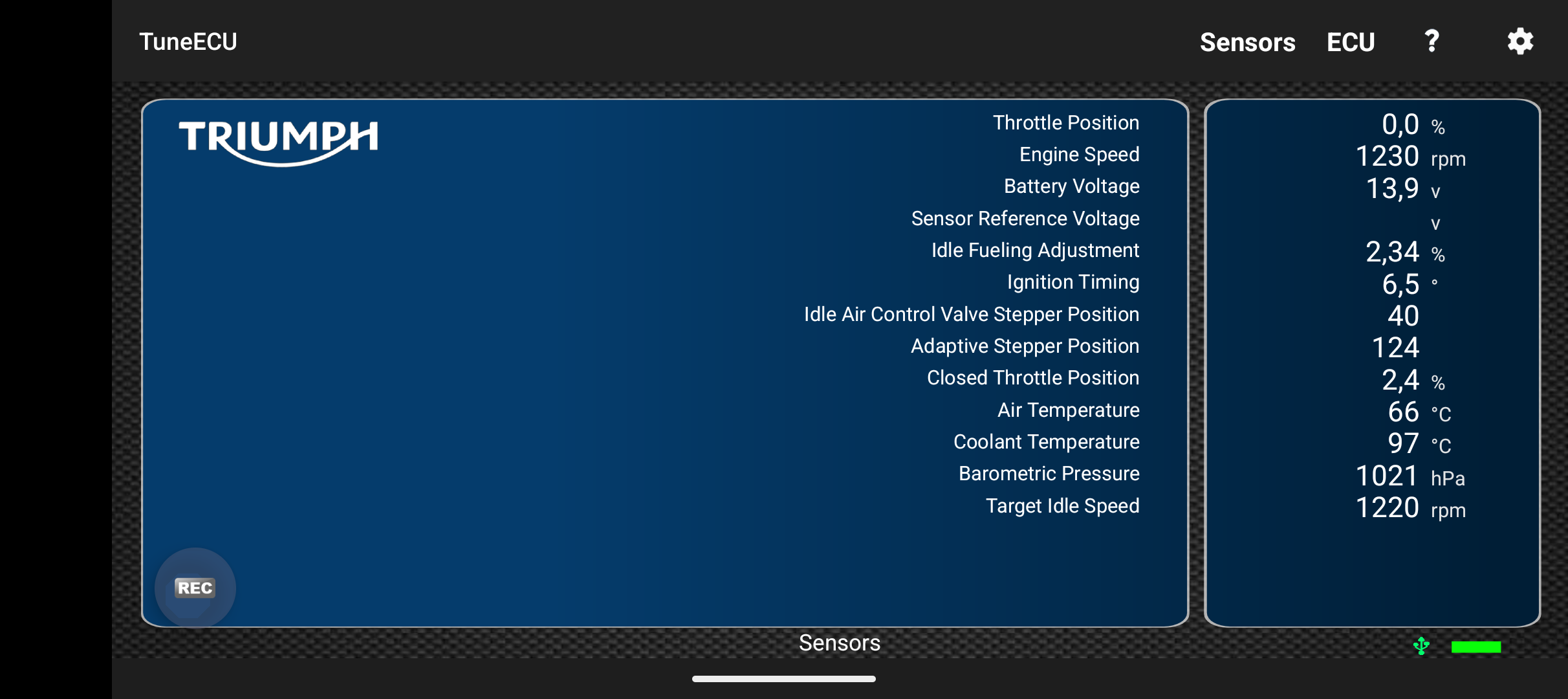
For context, 66c airbox temp is still hot but it had been idling until the cooling fan came on, in the full power of the sun with an ambient temp of 35c outside
It was such a silly issue but took me a hot minute to properly diagnose (didn’t help that the OBD scanner got lost in transit and took a while to arrive).
Here is a quick clip of it doing the 12min idle until the fan comes on:
Here is a quick clip of it revving happily after:
Custom Parts
During the rebuilding of this bike I ran into quite a few issues where either custom parts were needed or where it was just a good excuse to use the CNC machine.
I’ve made all parts that I designed freely available for anyone to use for their own personal projects (not for commercial use).
All parts and more can be found on my Printables, I’ve also included links to the individual parts in each section below.
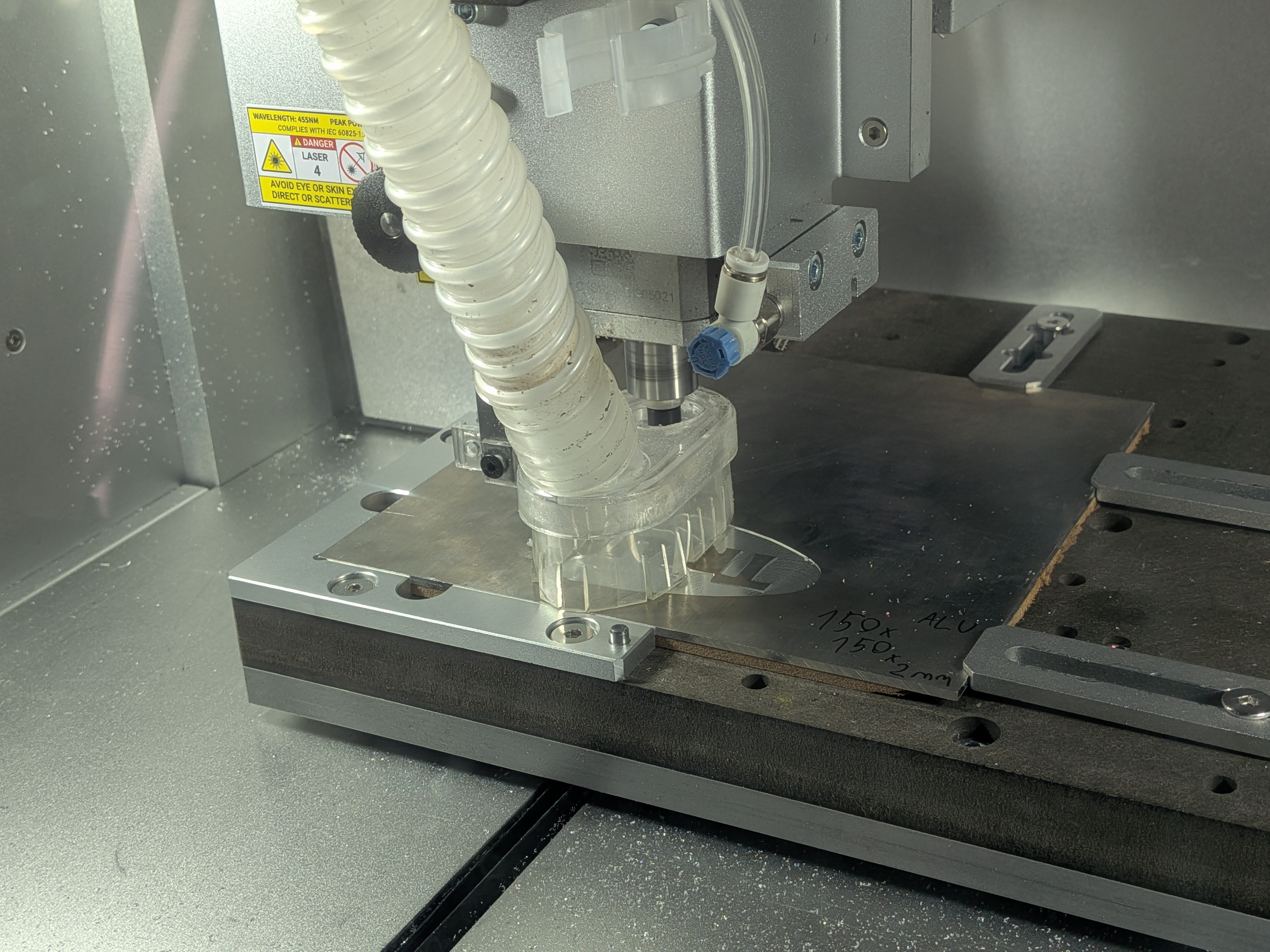
I made all these parts on a Makera Carvera.
Here is a quick clip of some of the machining I did (audio warning):
Disclaimer: The use of any of these parts is soley and exclusively at your own risk! I am not personally liable for any damages, malfunctions or injuries caused by using these parts.
Headlight Bracket
When I got the bike the headlights were held together using the bracket of a 675/1050 Street/Speed triple. This made it so I couldn’t physically install the nuts to secure the headlights in place, which left the headlights flopping around.
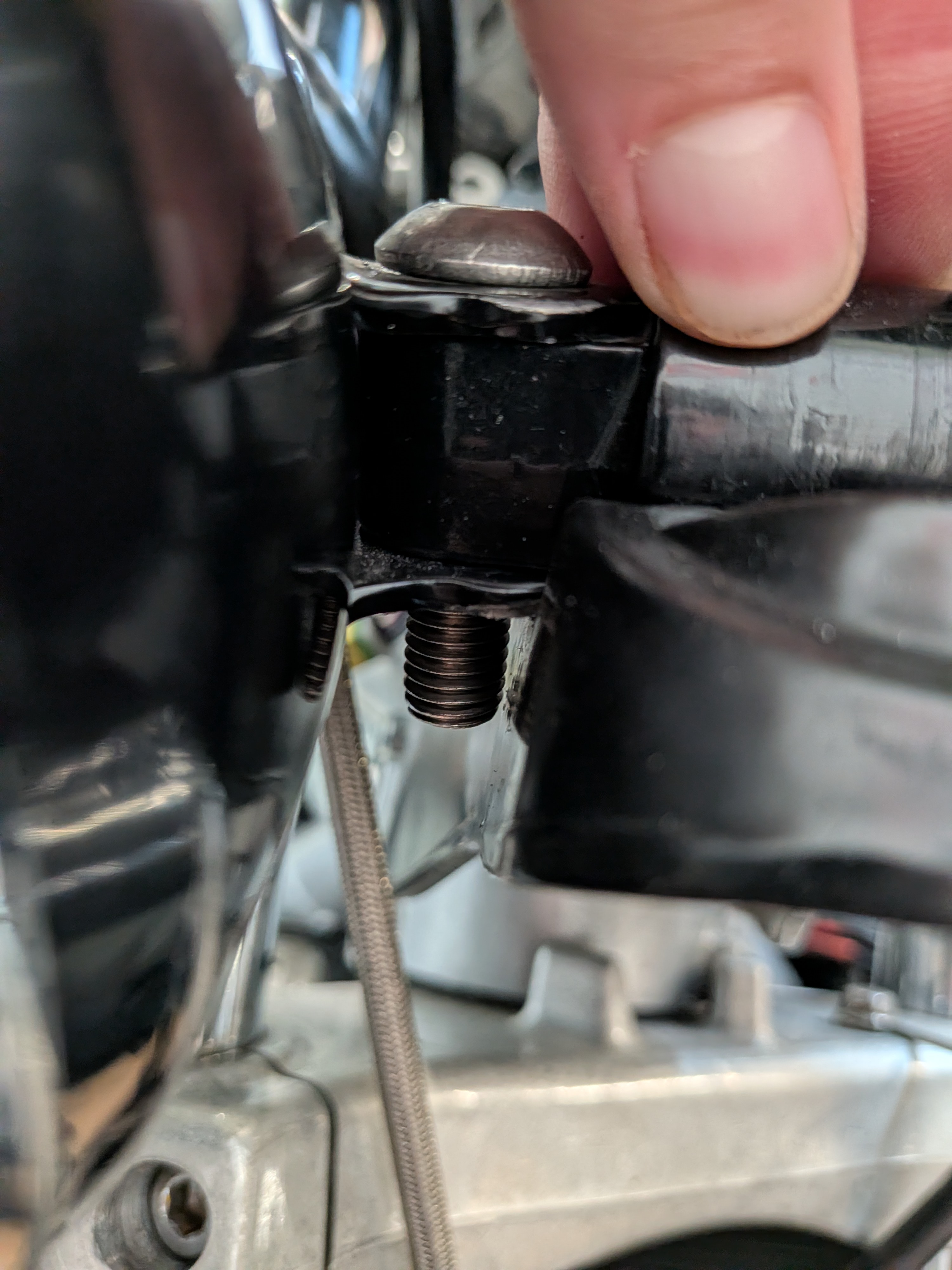
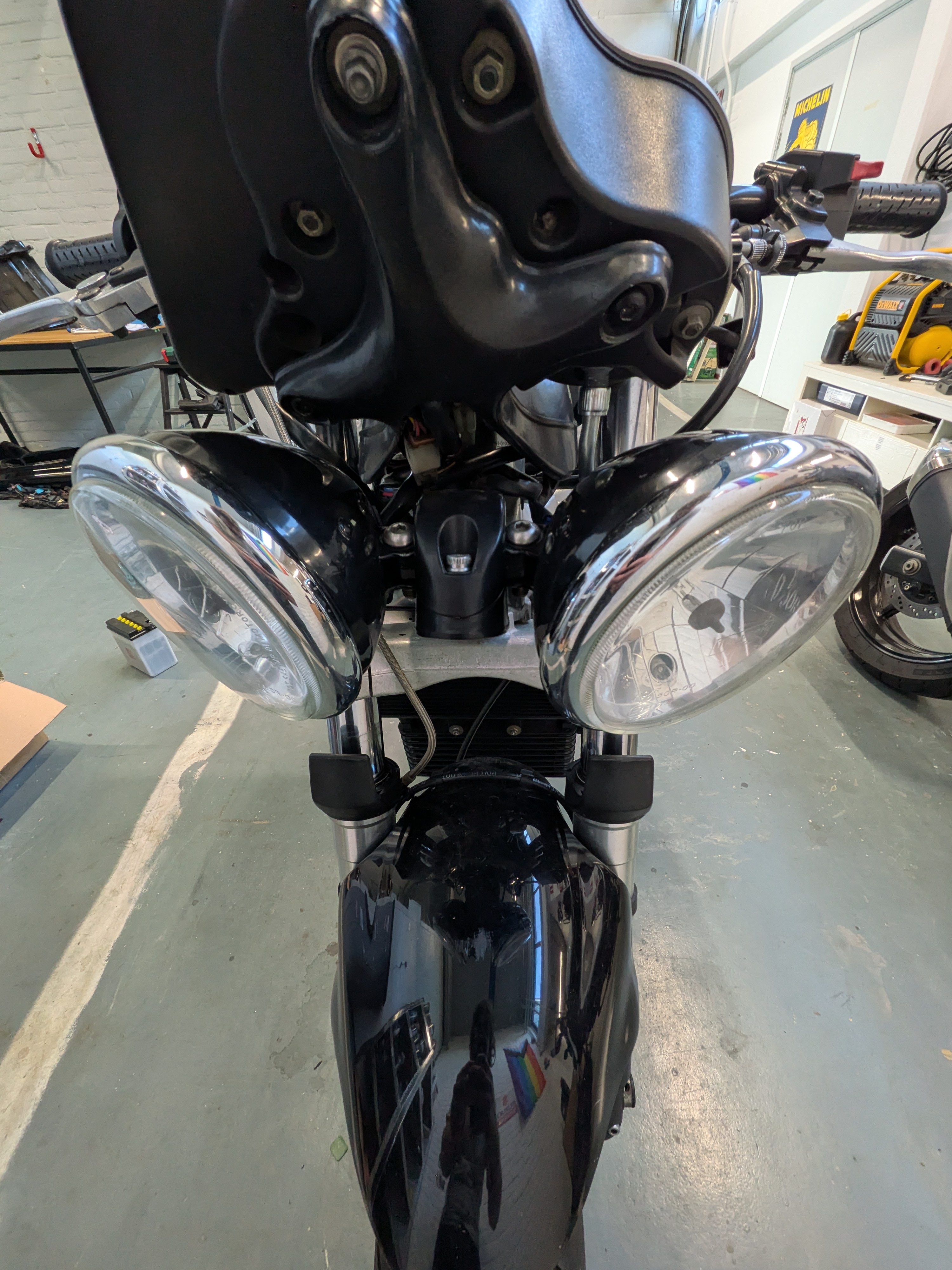
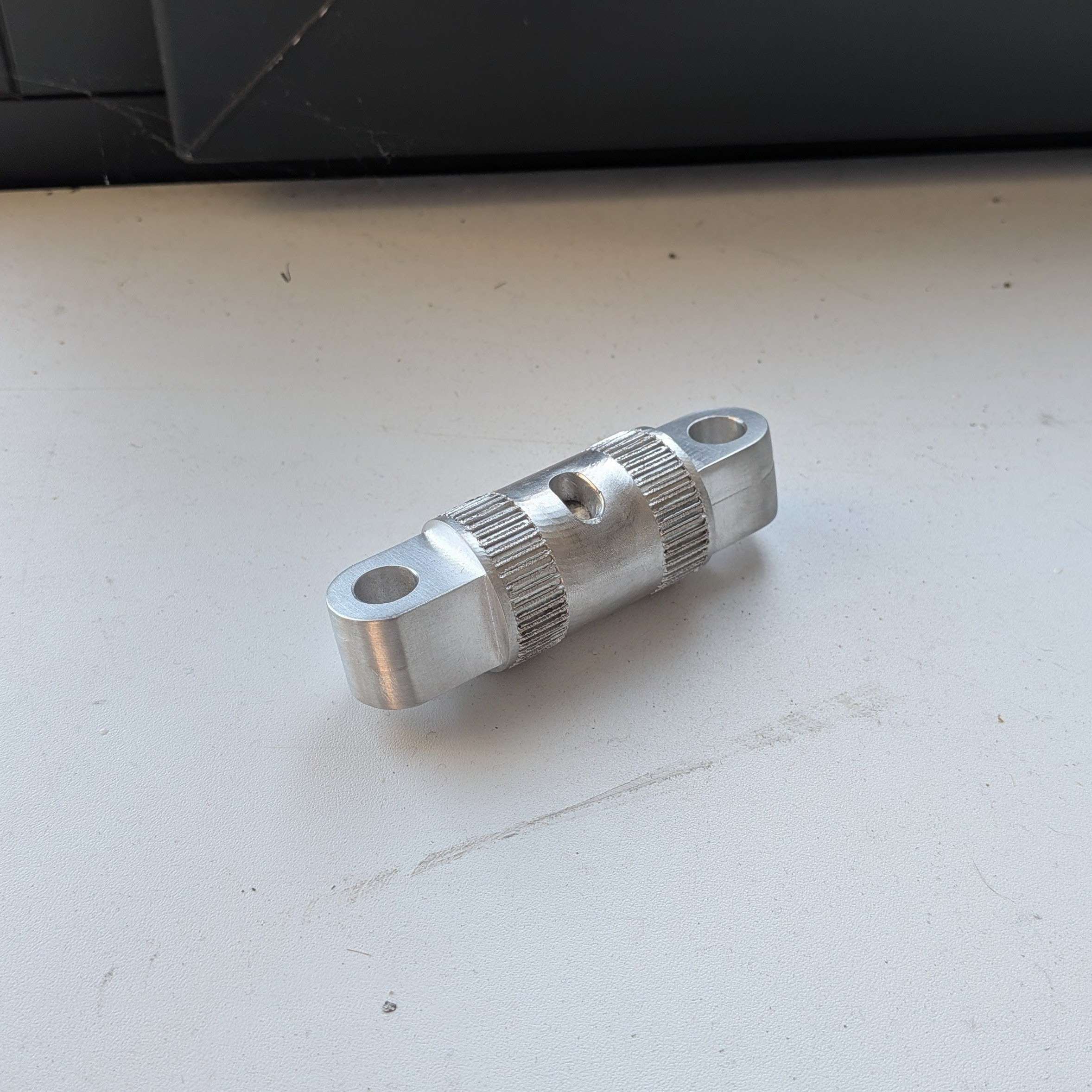
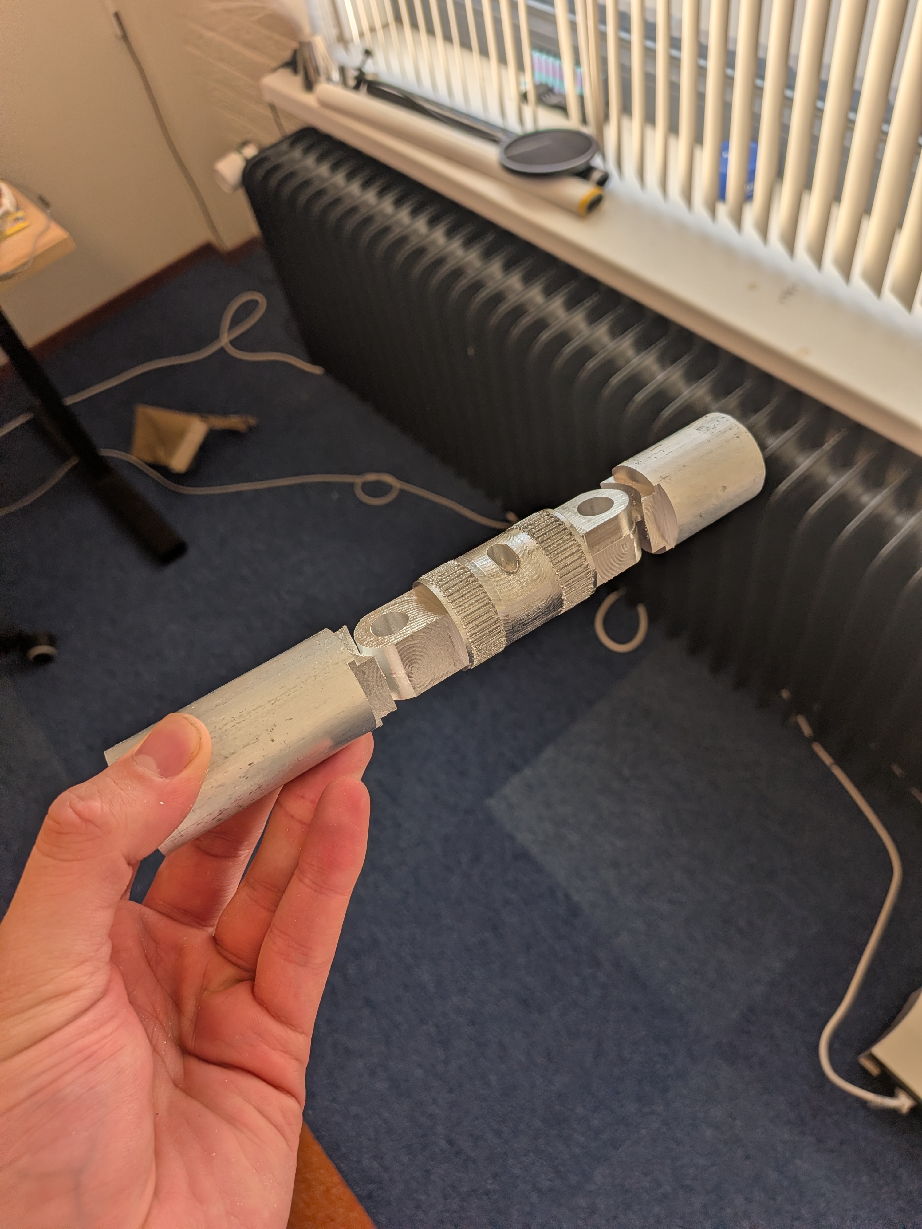
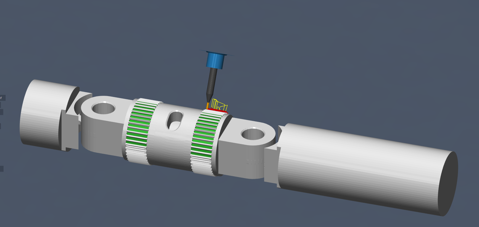
So I designed and manufactured my own correct part based off of pictures and measurements I took on the bike itself. I did look at buying the piece but thought the options were all way too expensive.
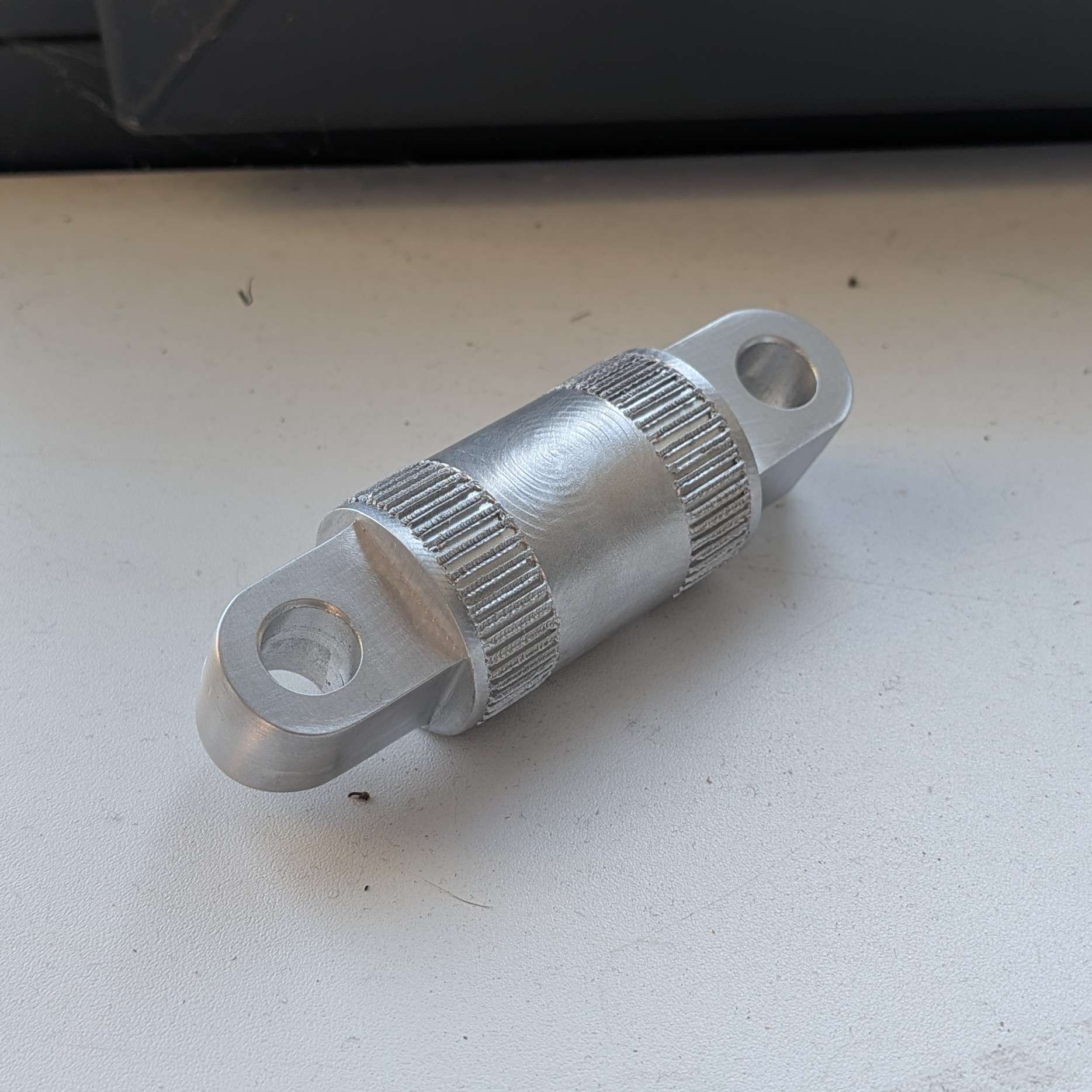
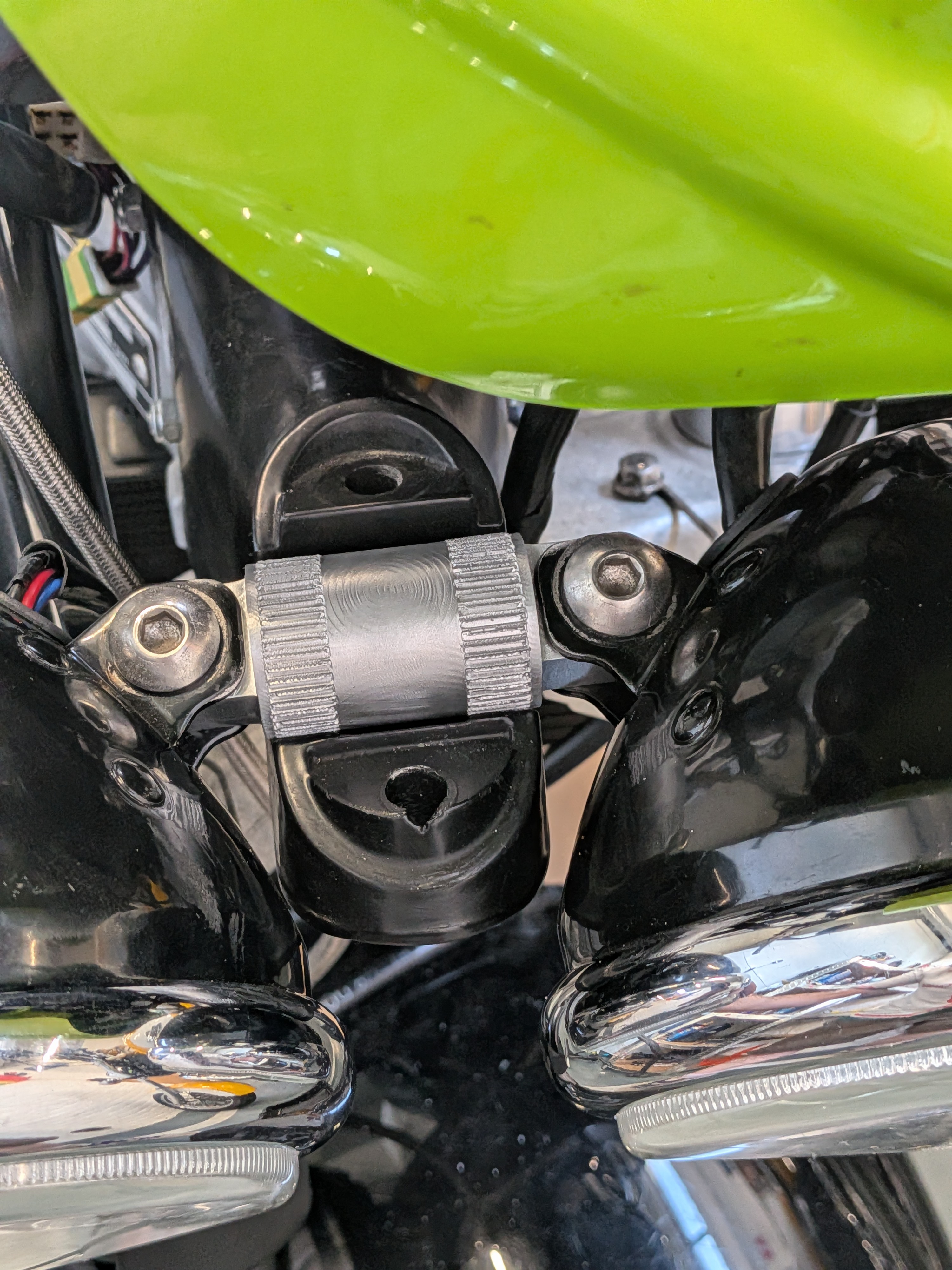
More photos of the part and production process.
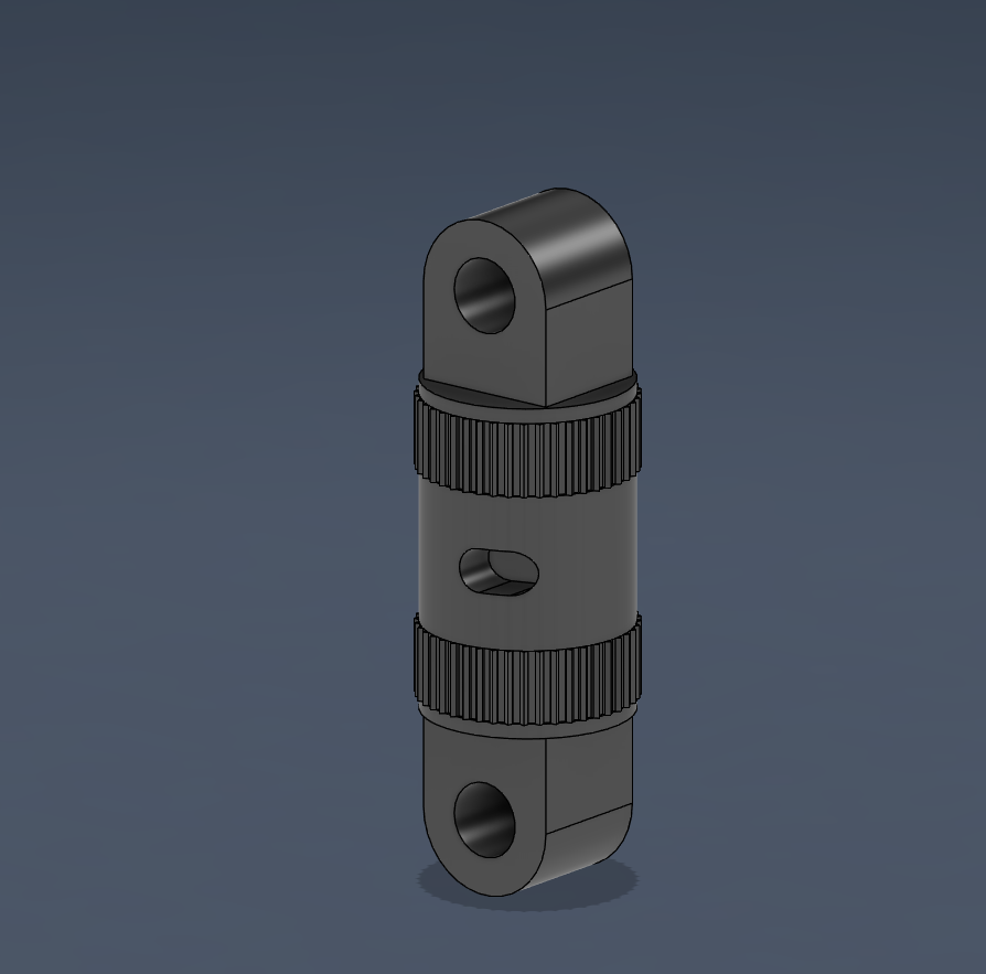
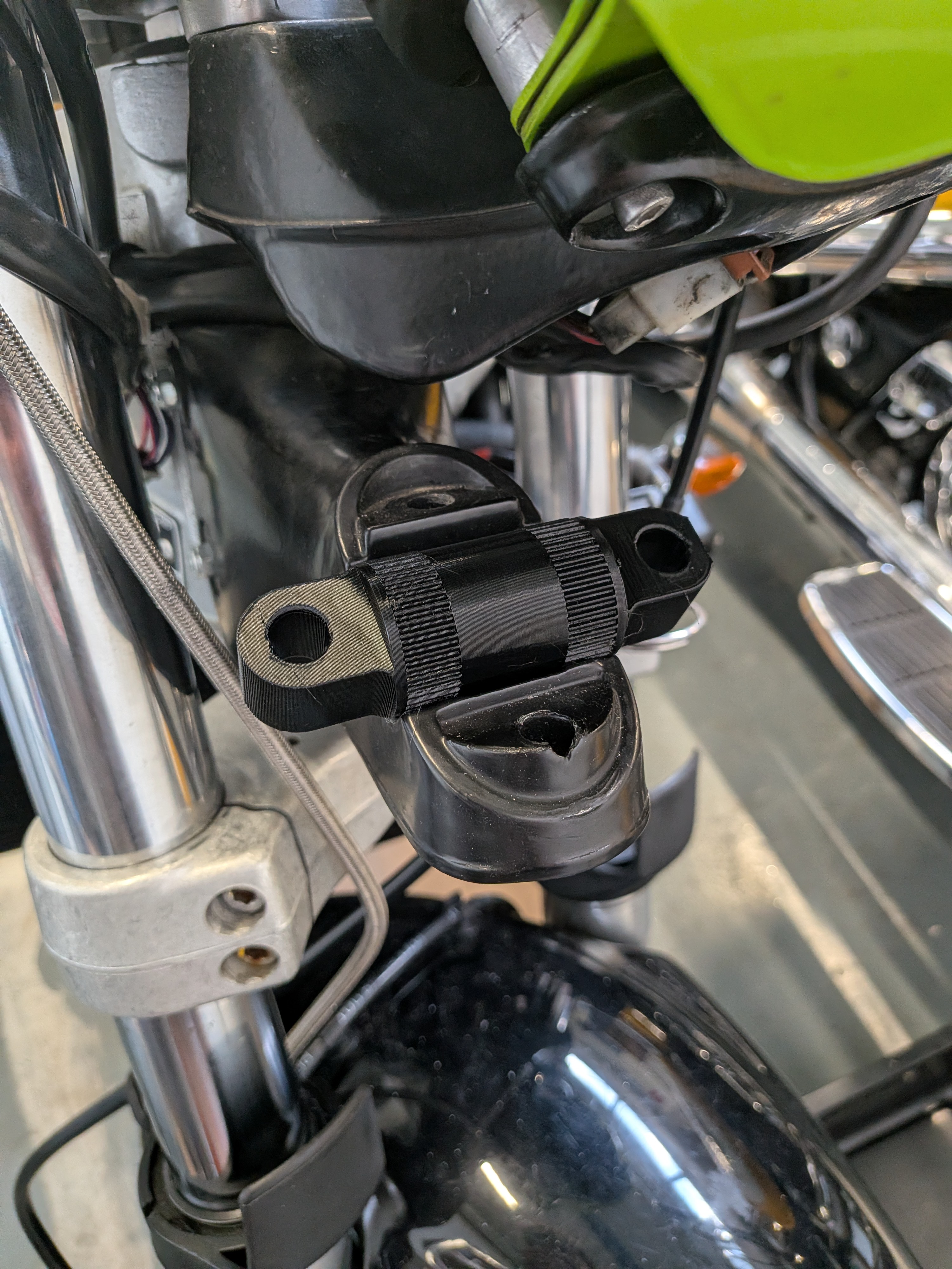
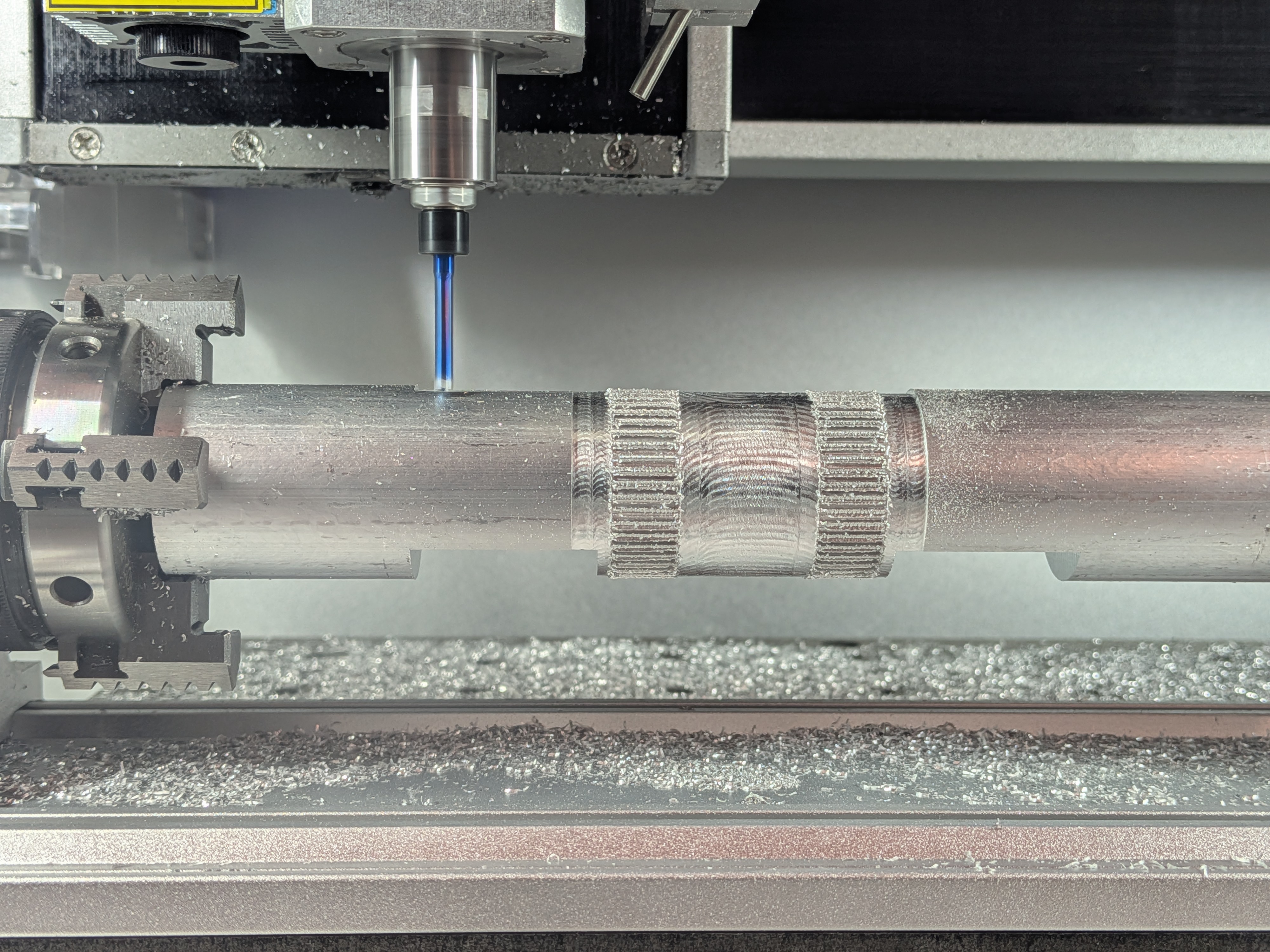
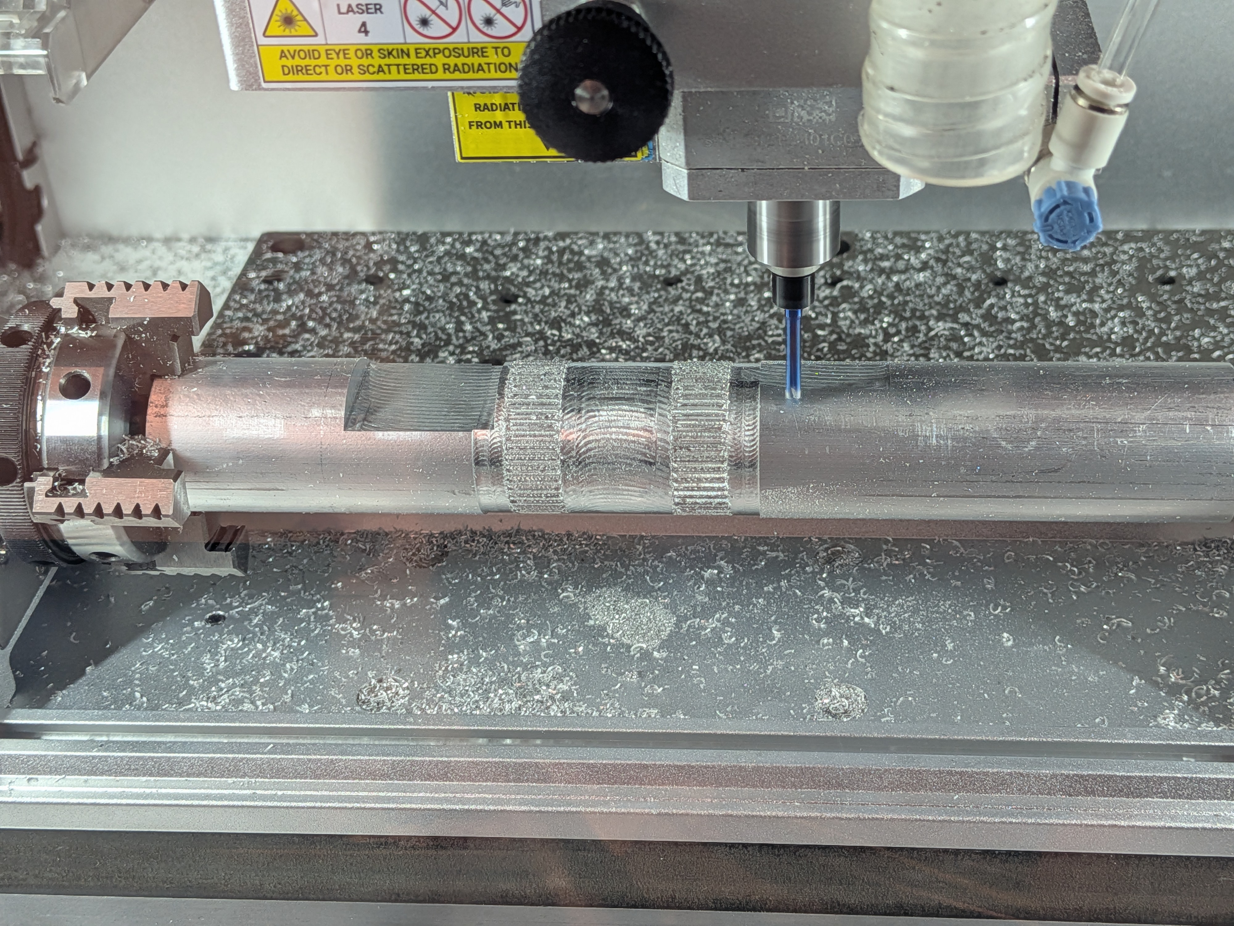
Right click or long press to view full-size image in a new tab
You can find the files here.
Footguard
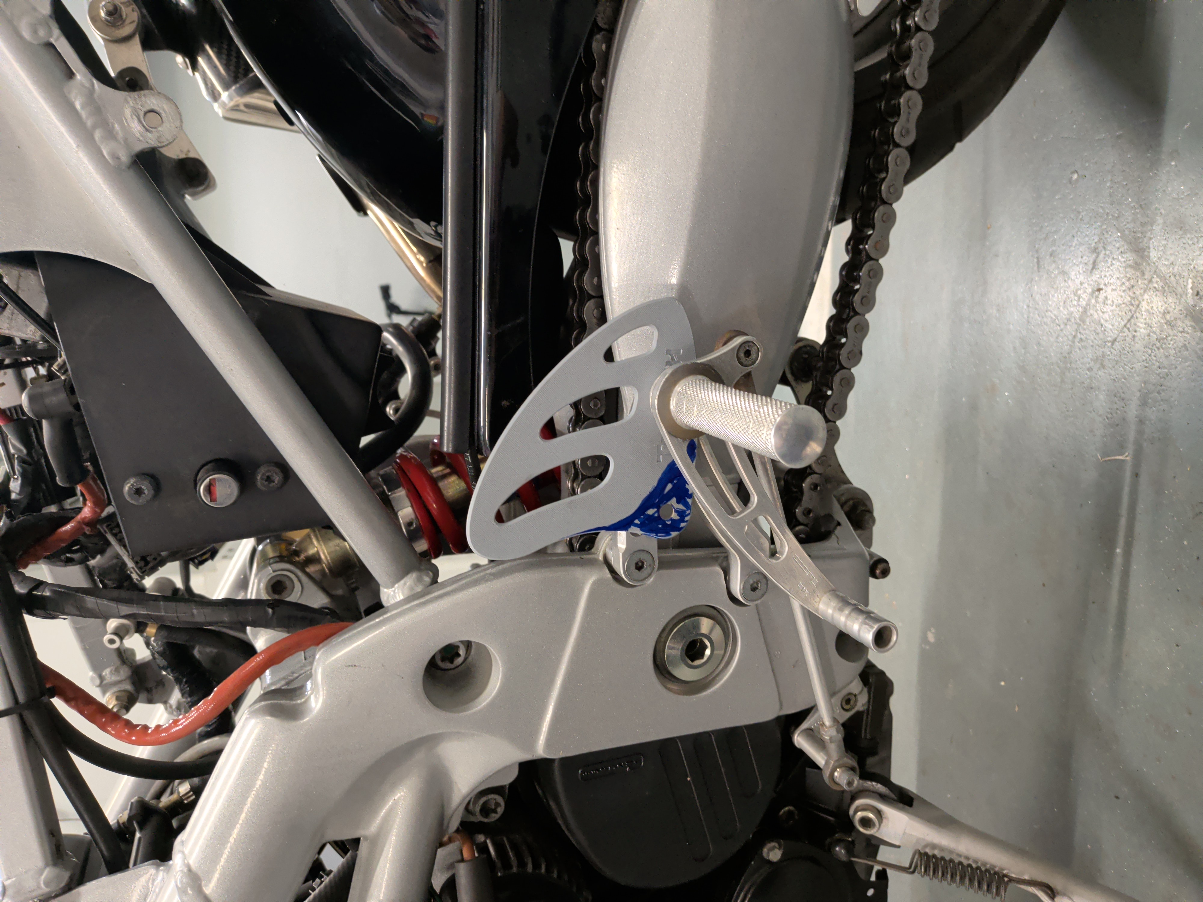
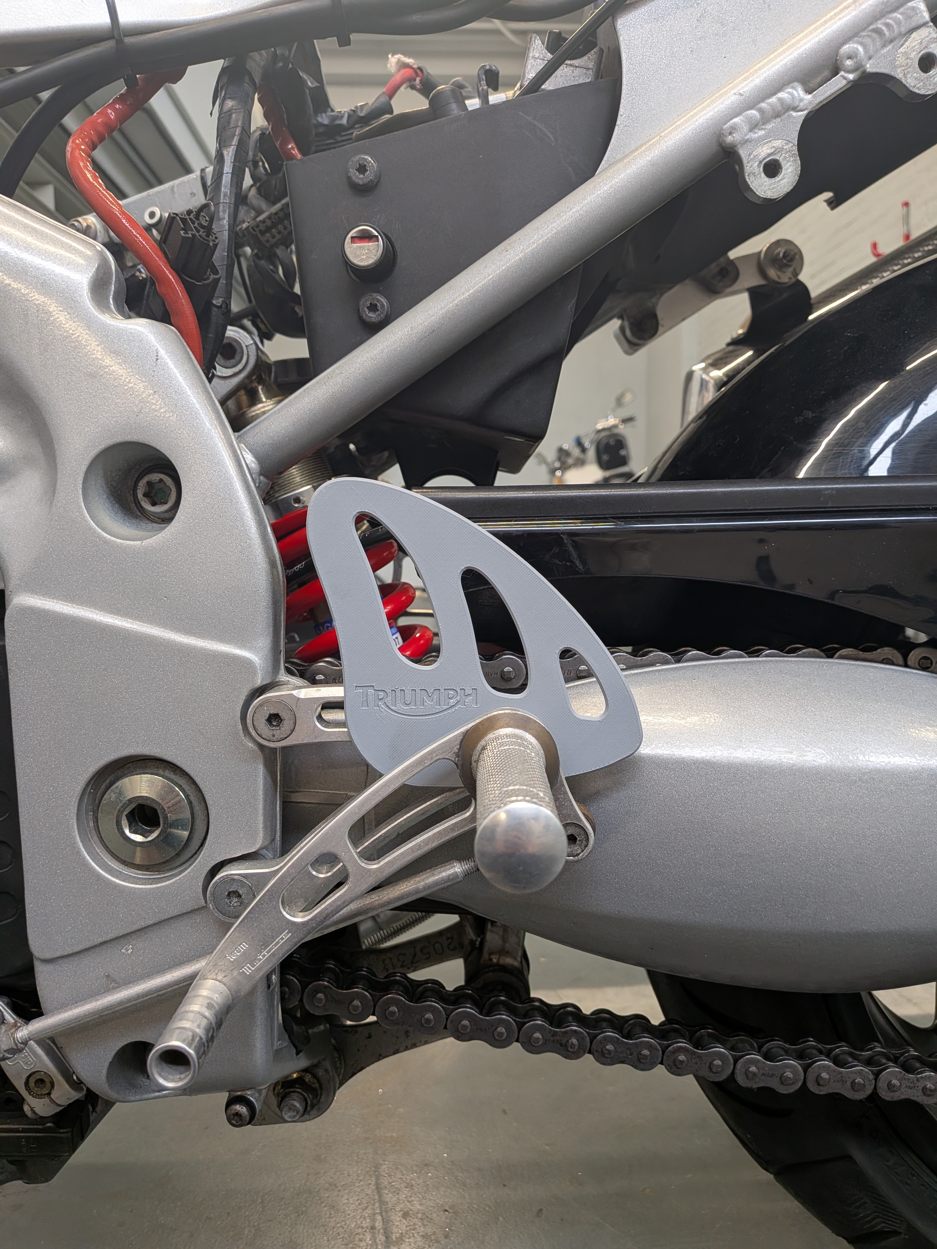
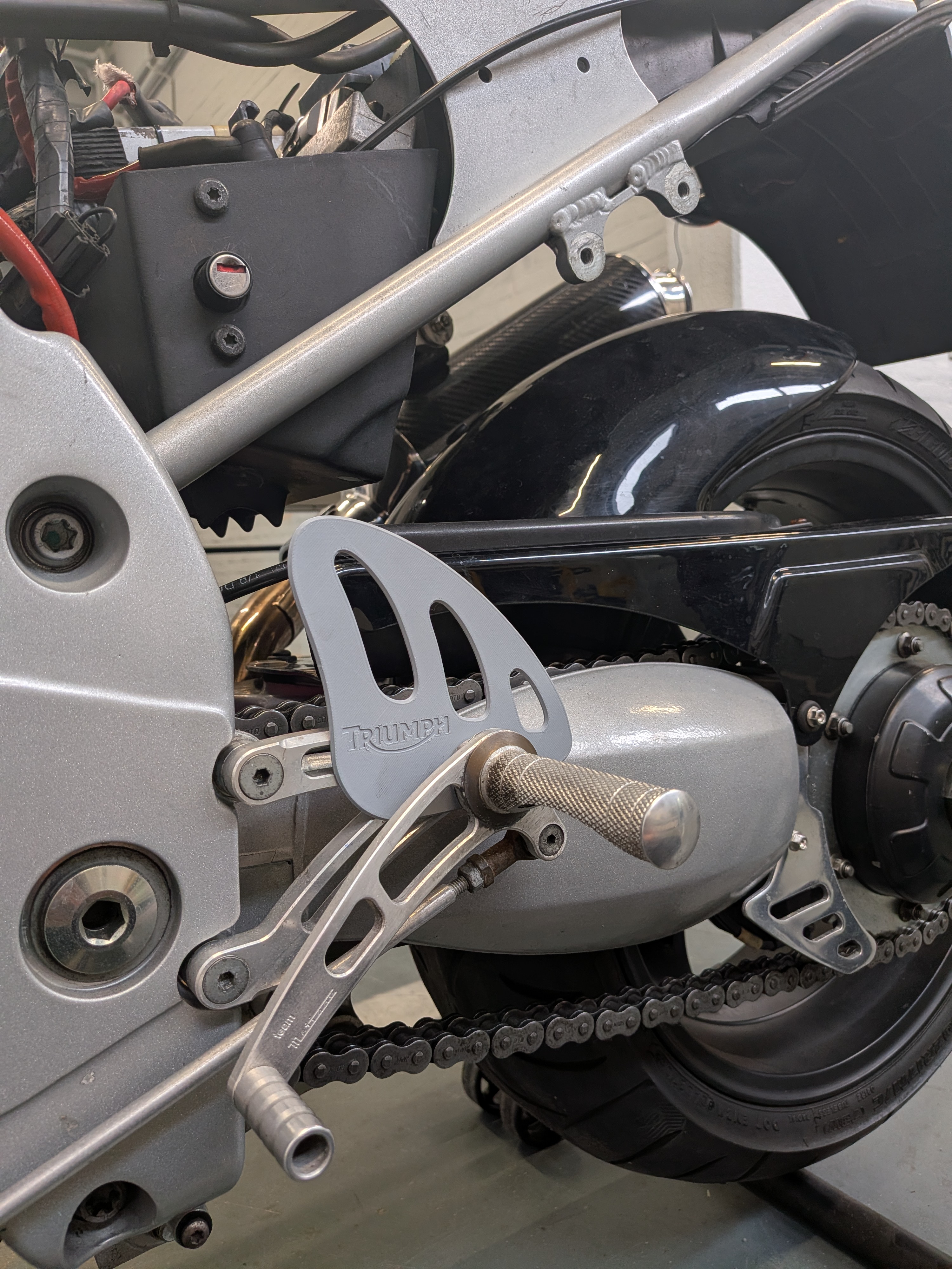
When I got the bike it was already fitted with aftermarket rearsets by a brand called “Team Metisse”. These originally came with a carbon fiber foot guard, however this one had a massive crack in it.
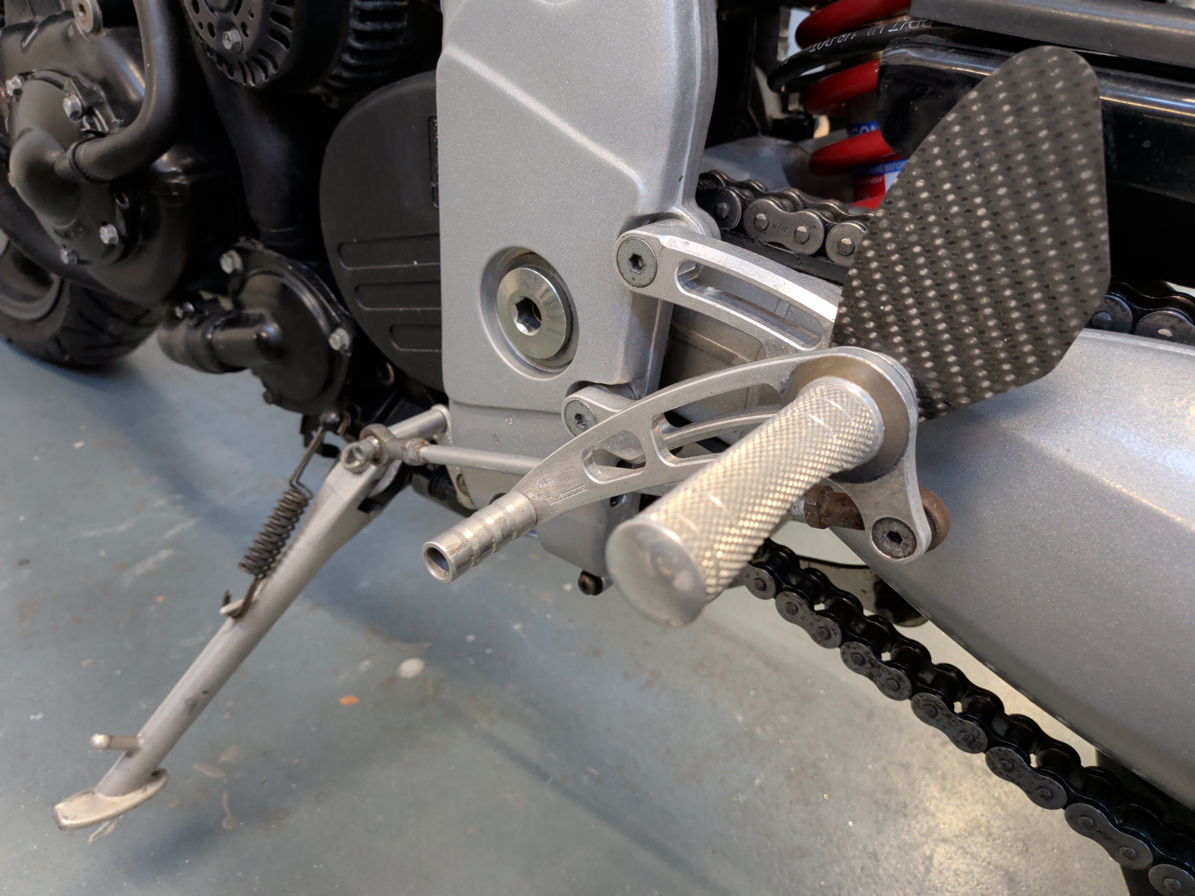
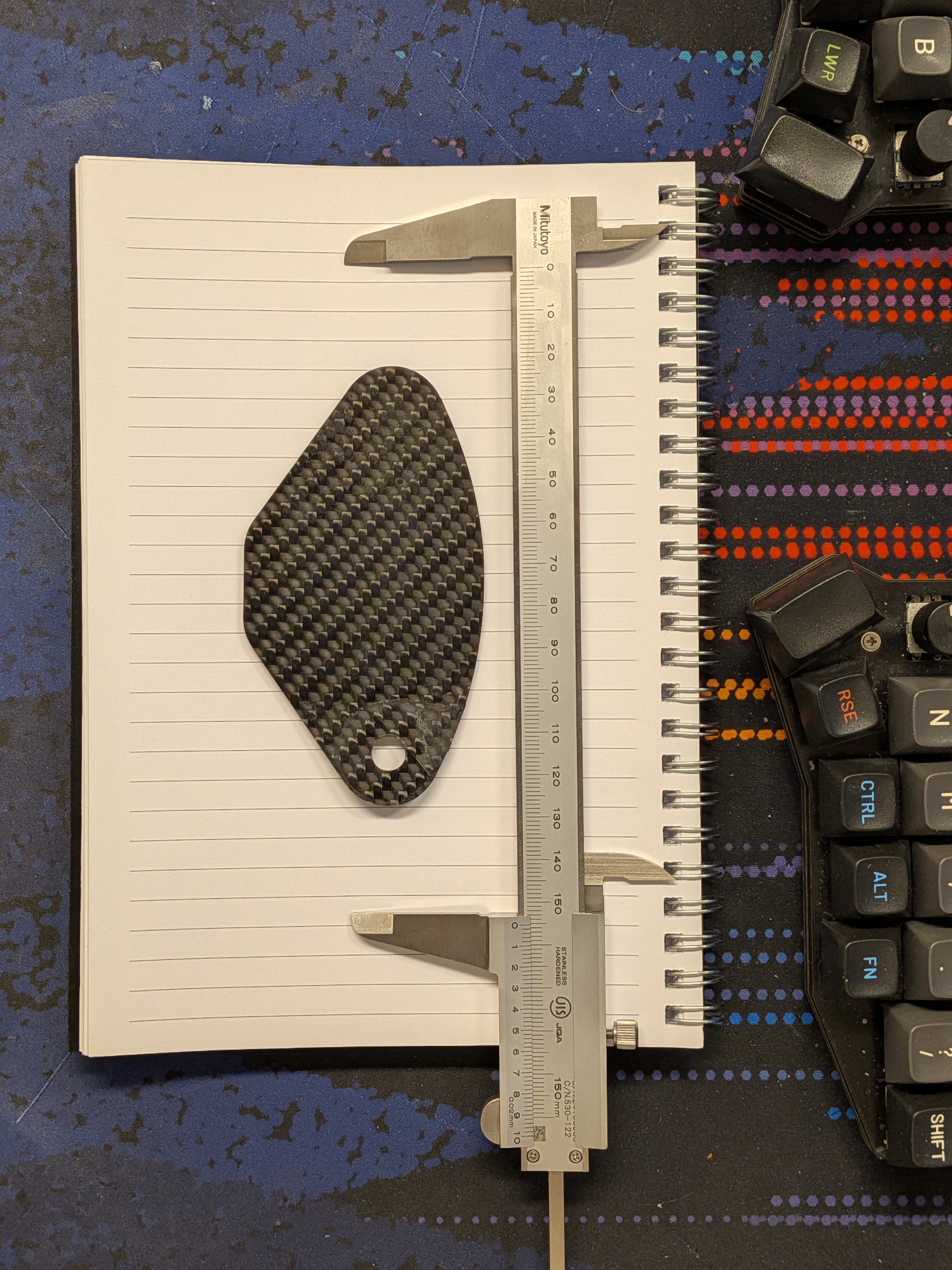
What I ended up doing is both create a 3D model replica of the original and design an entirely custom part from scratch to match the bike better.
This is what I ended up with:
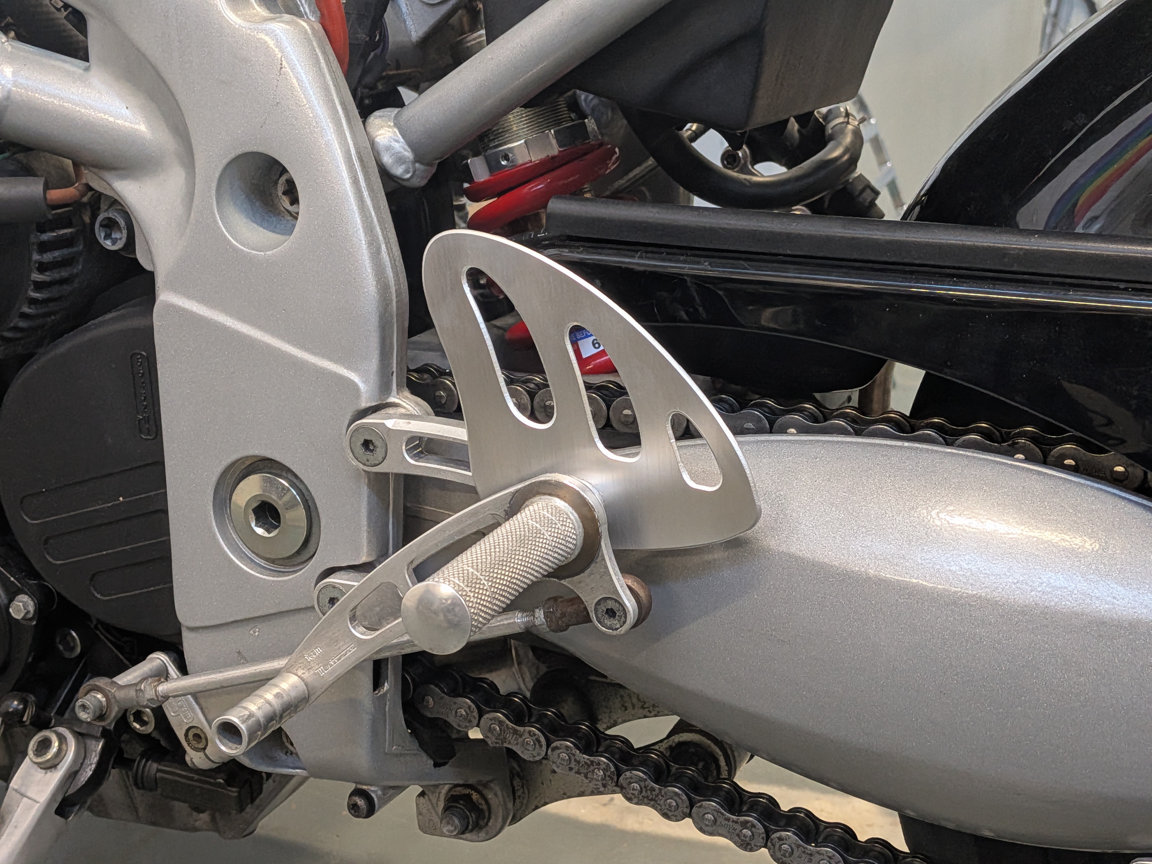
I tried a few different shapes and positions but eventually landed on the one in the image above.
Clearance with the swingarm was of great importance here, as too little could cause issues but too much and the foot guard would not serve it’s purpose.
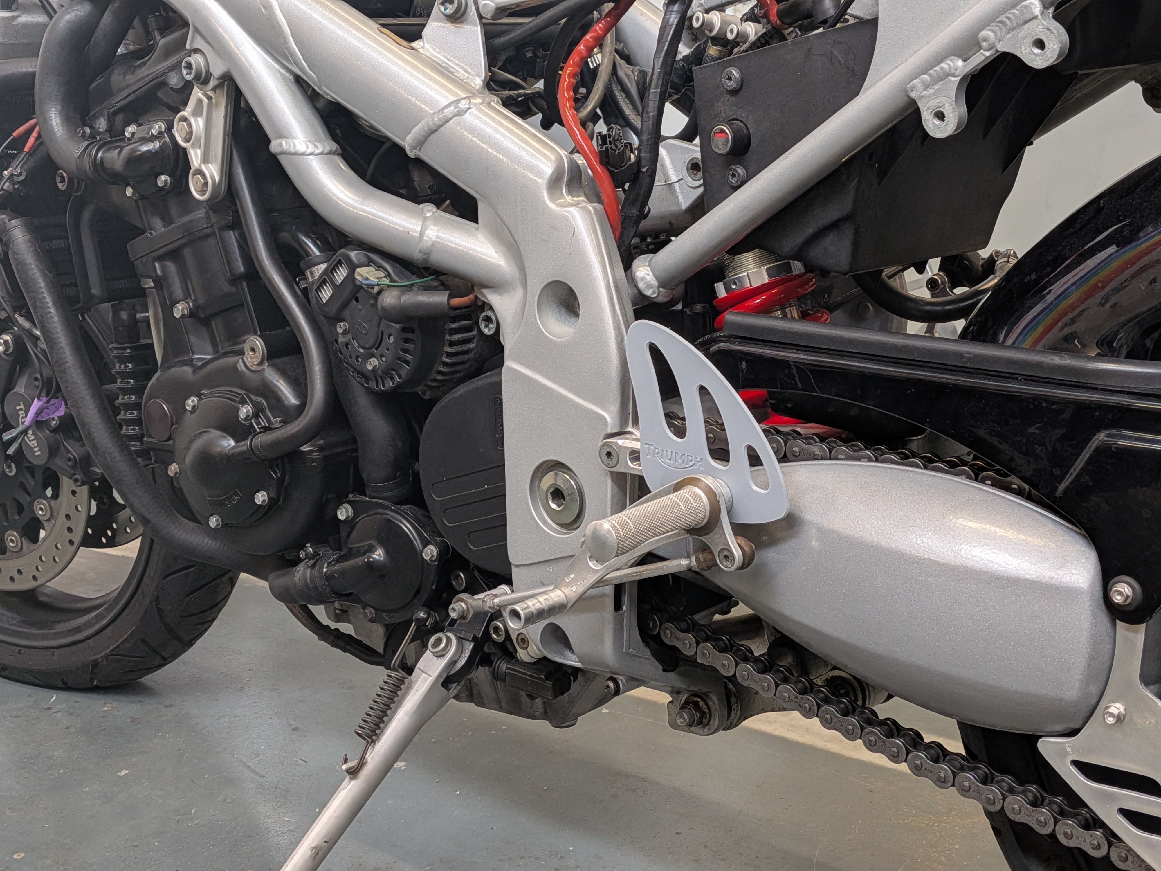
In the end I printed quite a few different versions, making small corrections with a marker until I was satisfied.
The final step was going to be engraving of the triumph logo, but I decided against it in the end.
More photos of the part and production process.
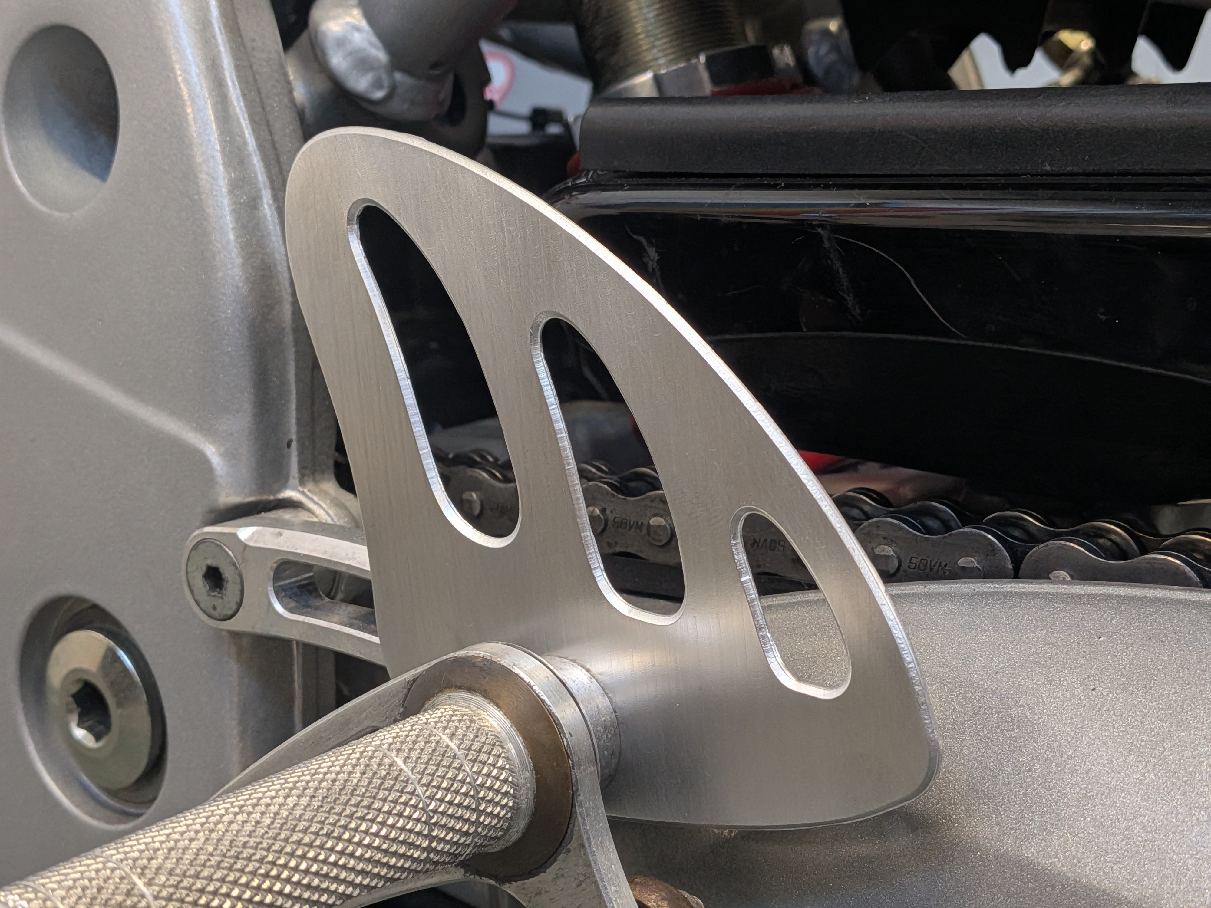
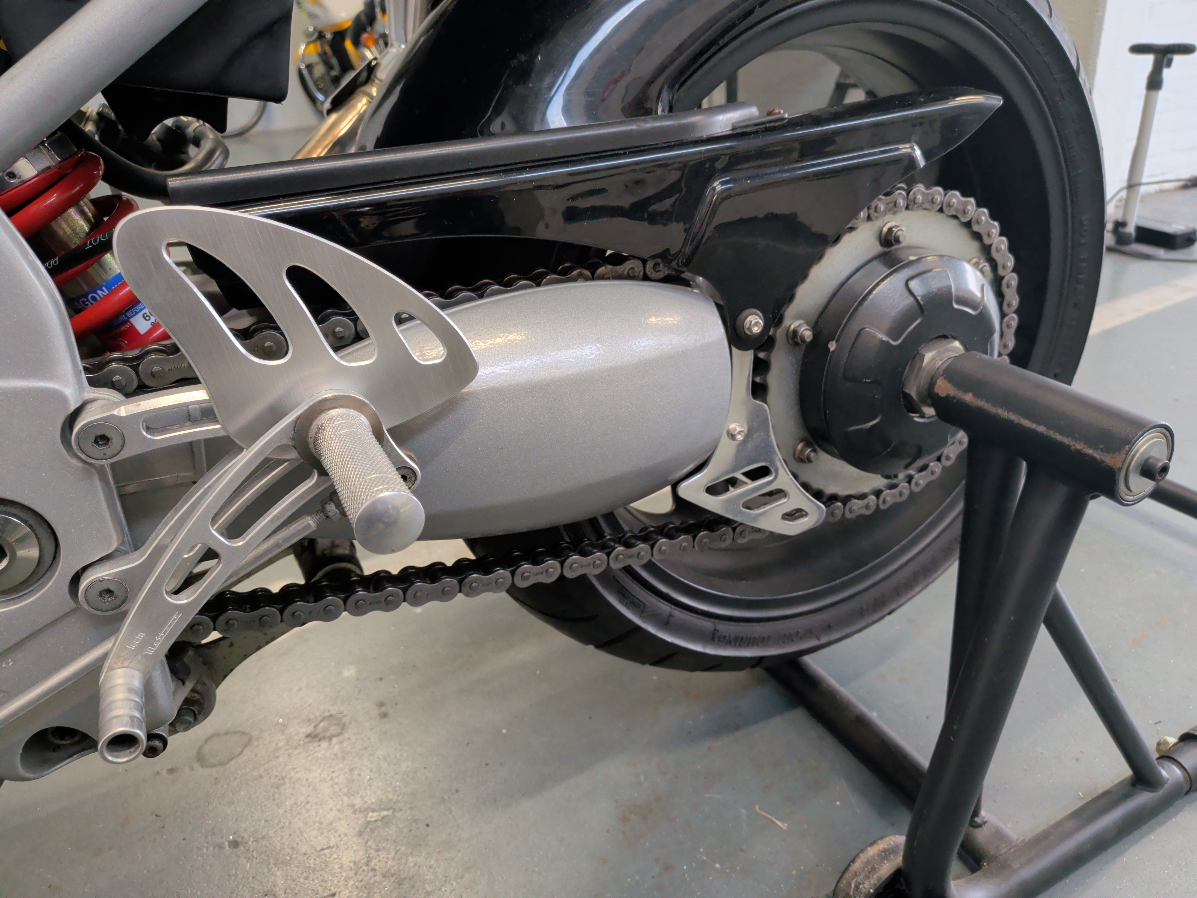
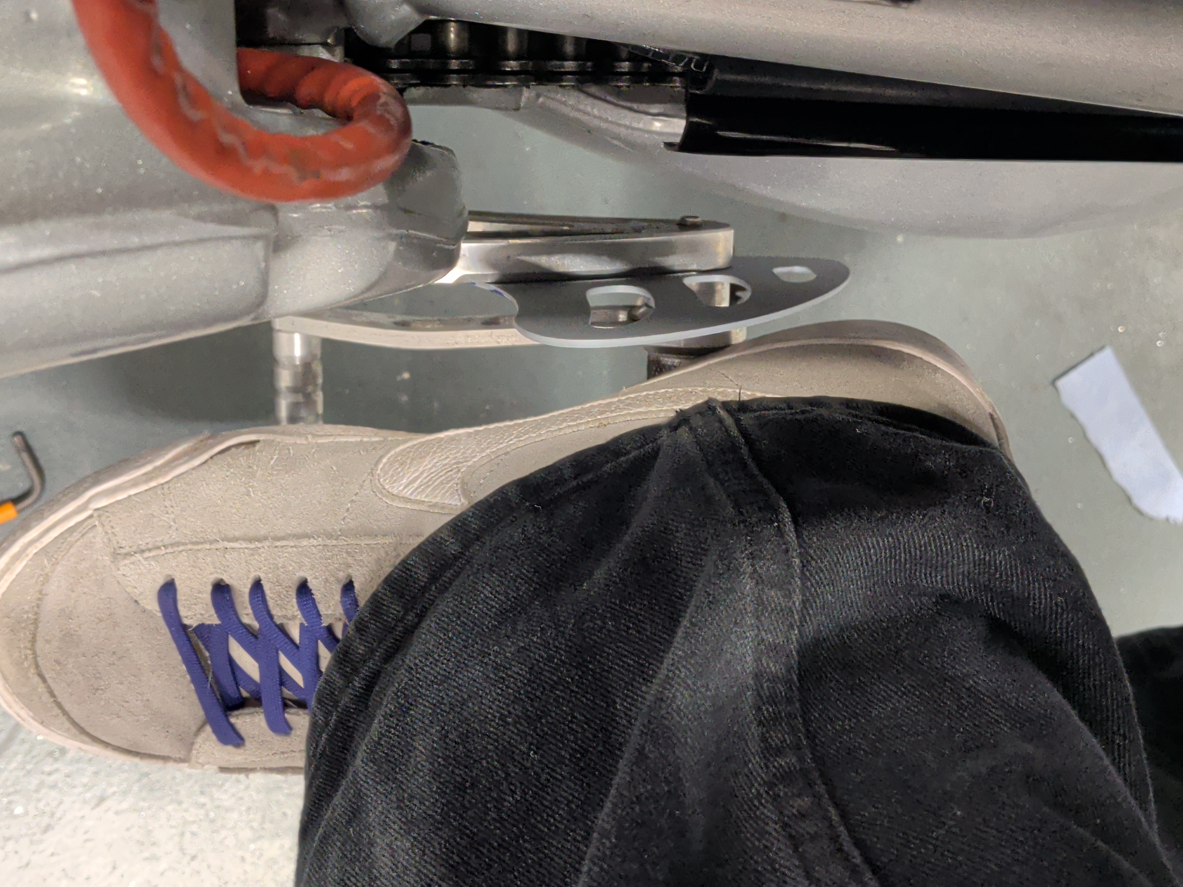
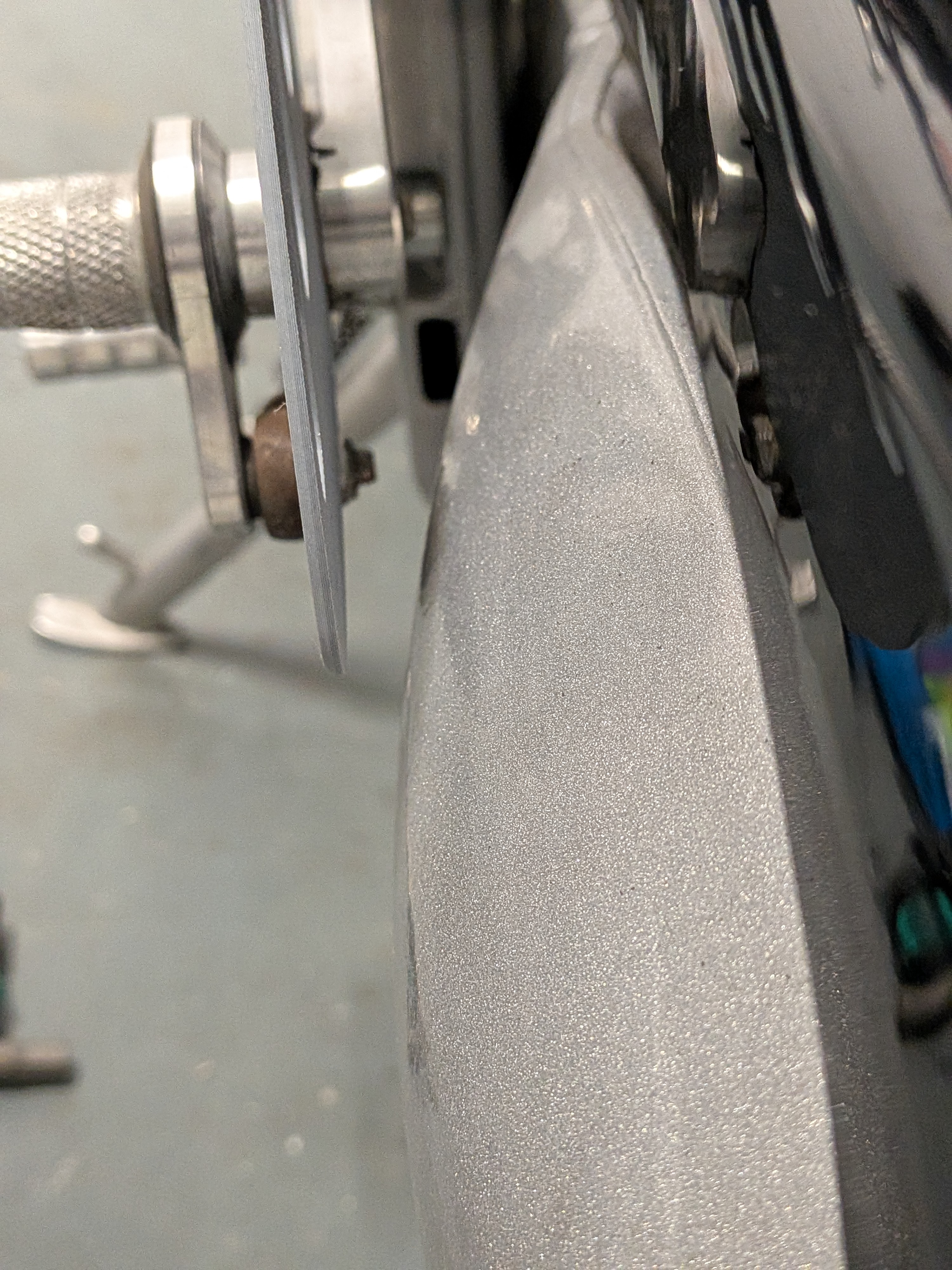
Right click or long press to view full-size image in a new tab
You can find these files here.
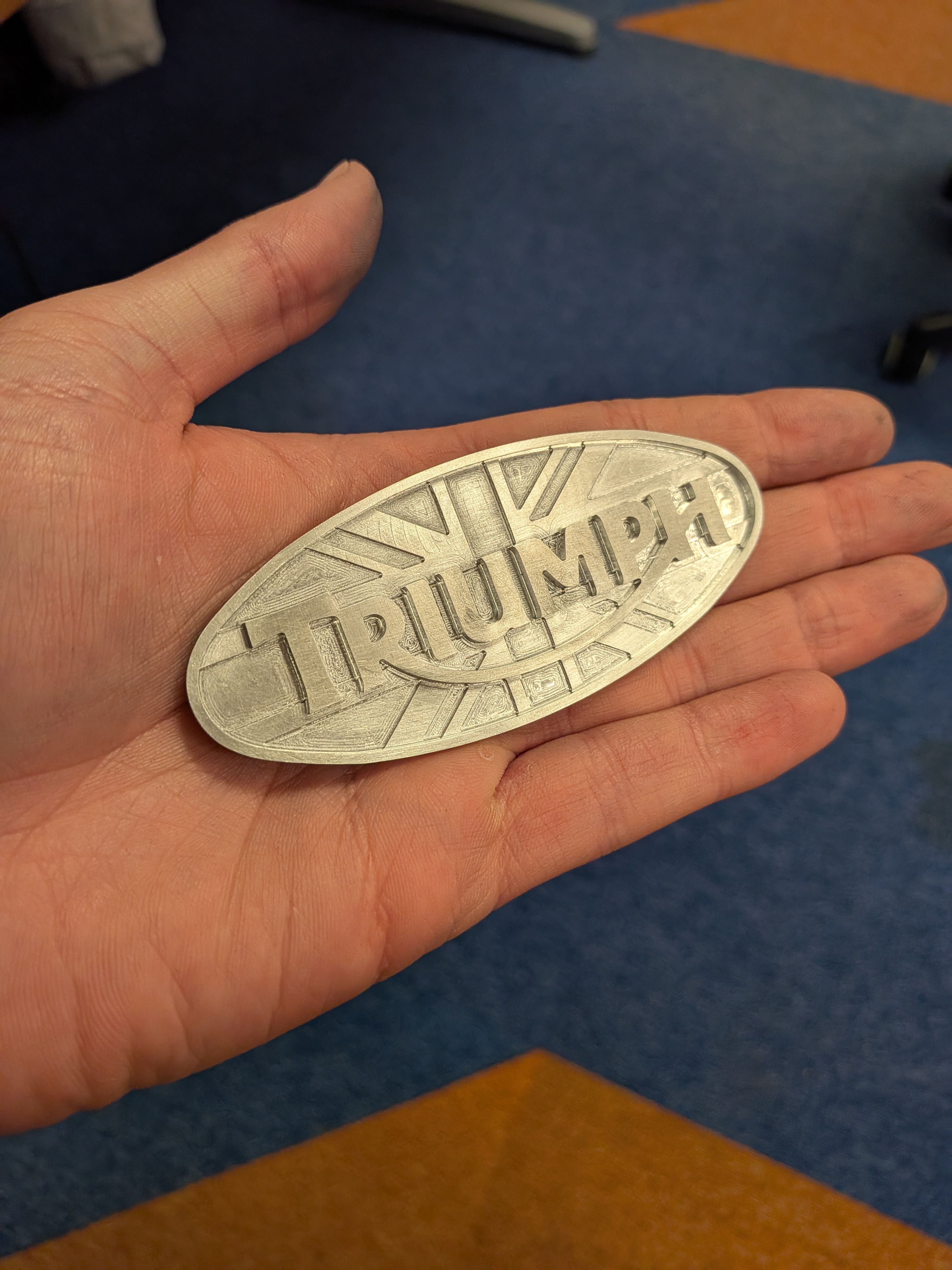
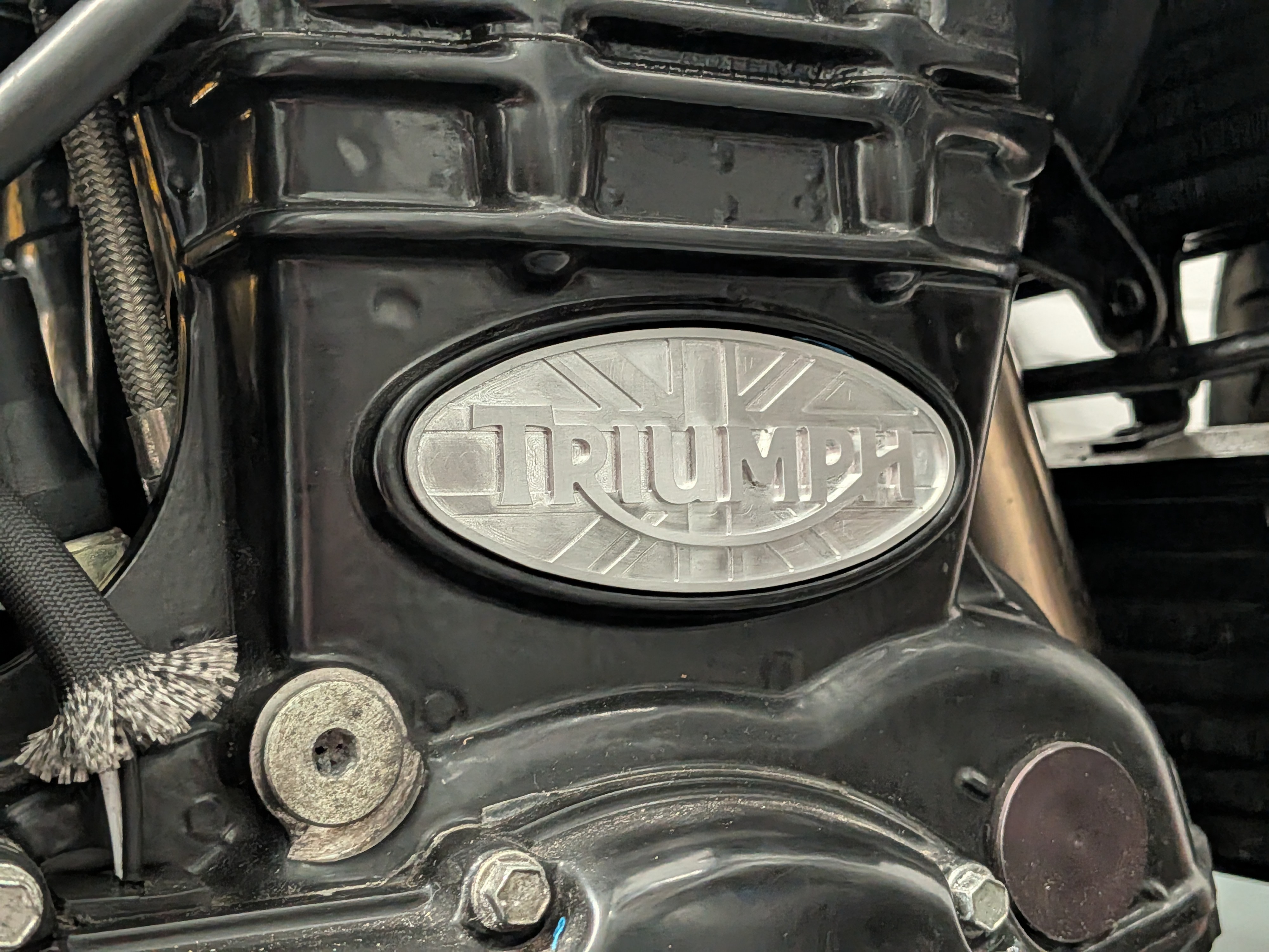
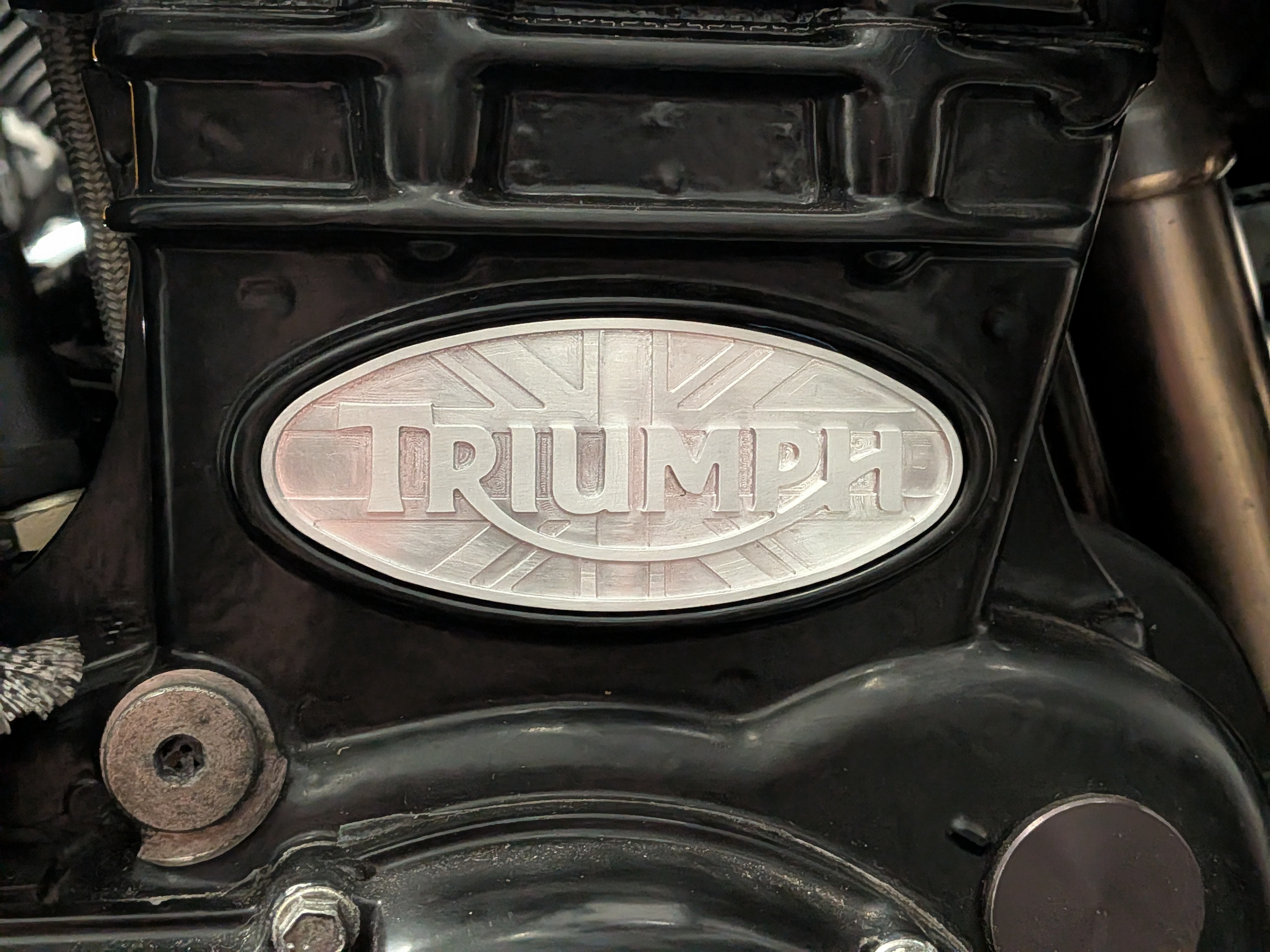
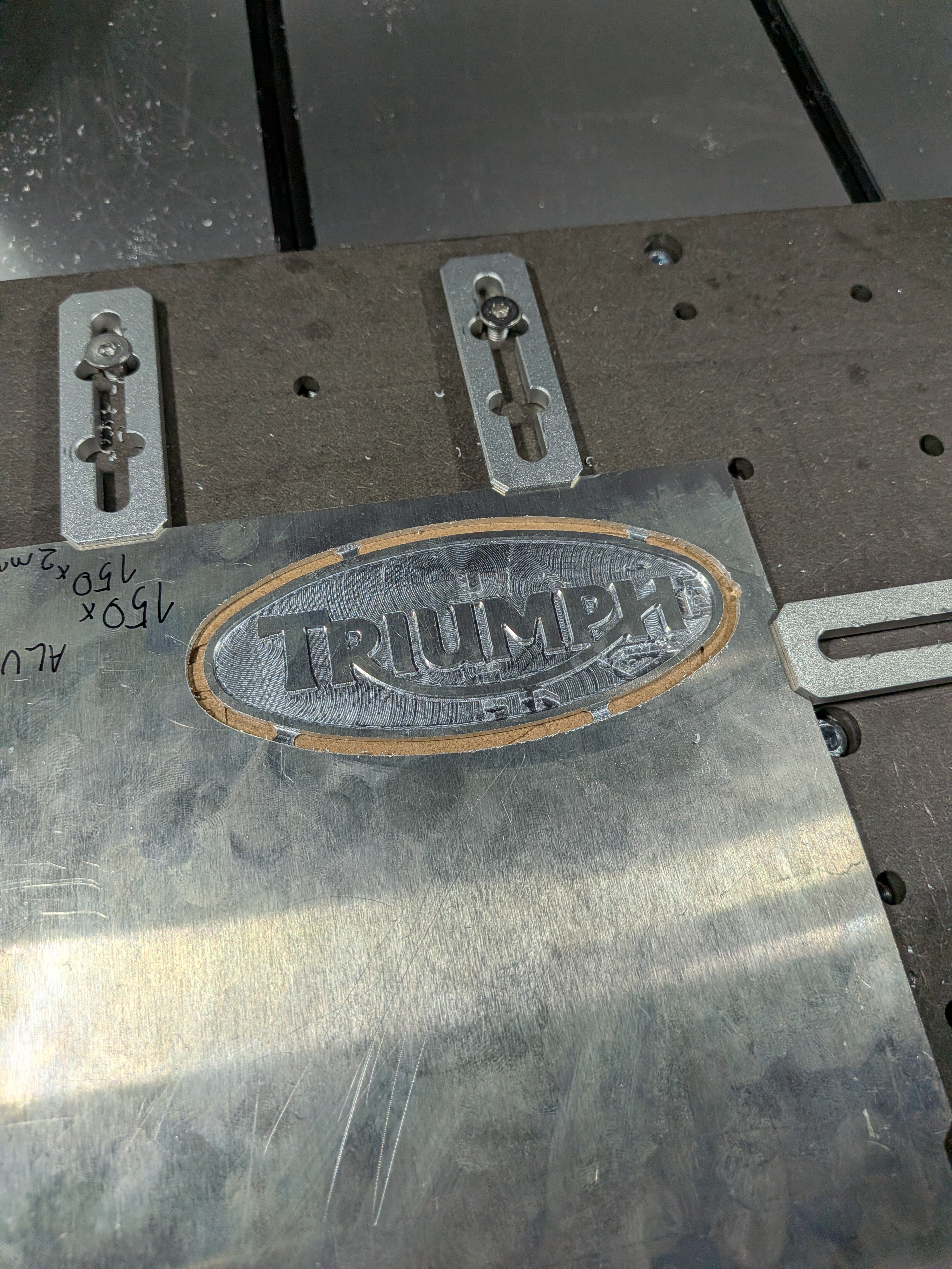
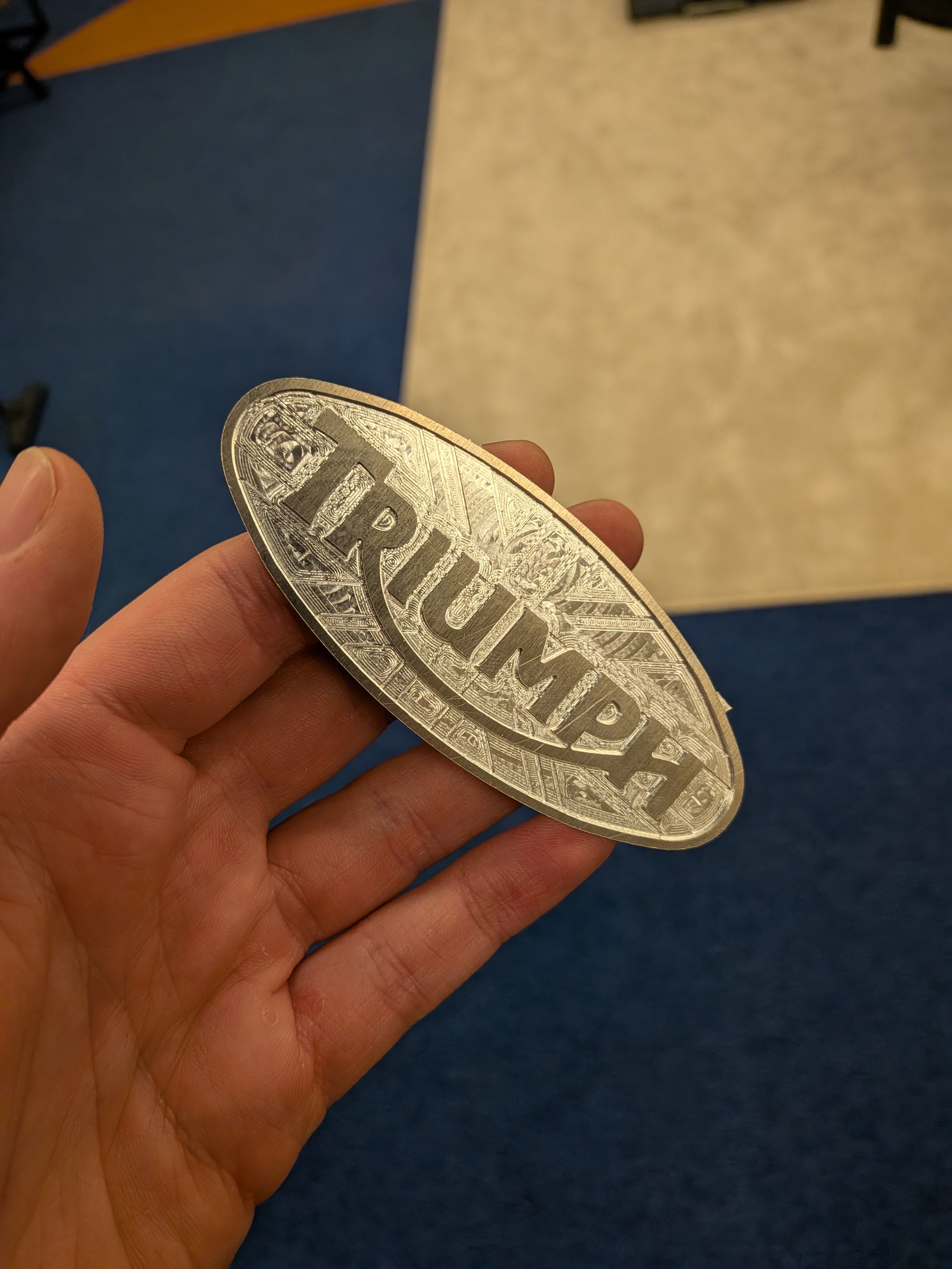
Engine Badge
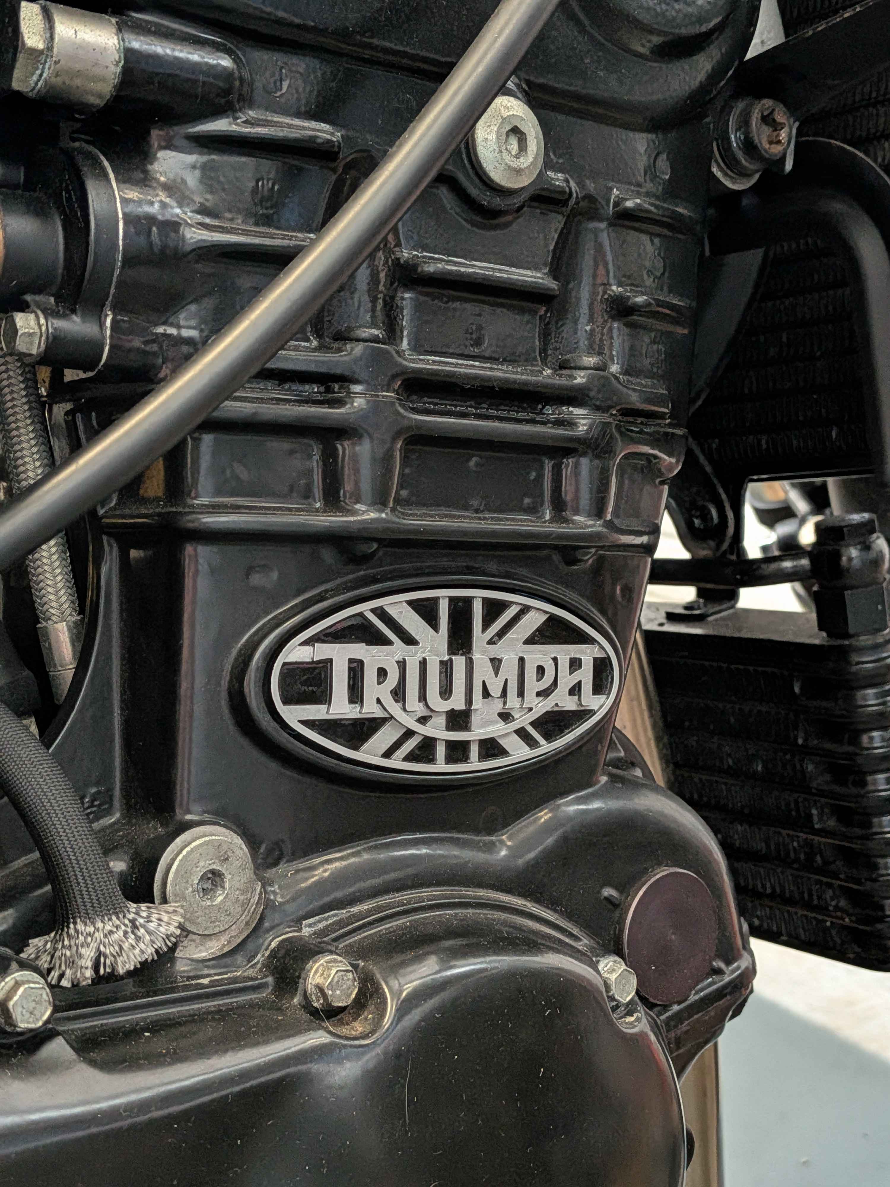
Because the bike started life as a Daytona instead of a Speed Triple it lacks the iconic badge on the right hand side of the engine.
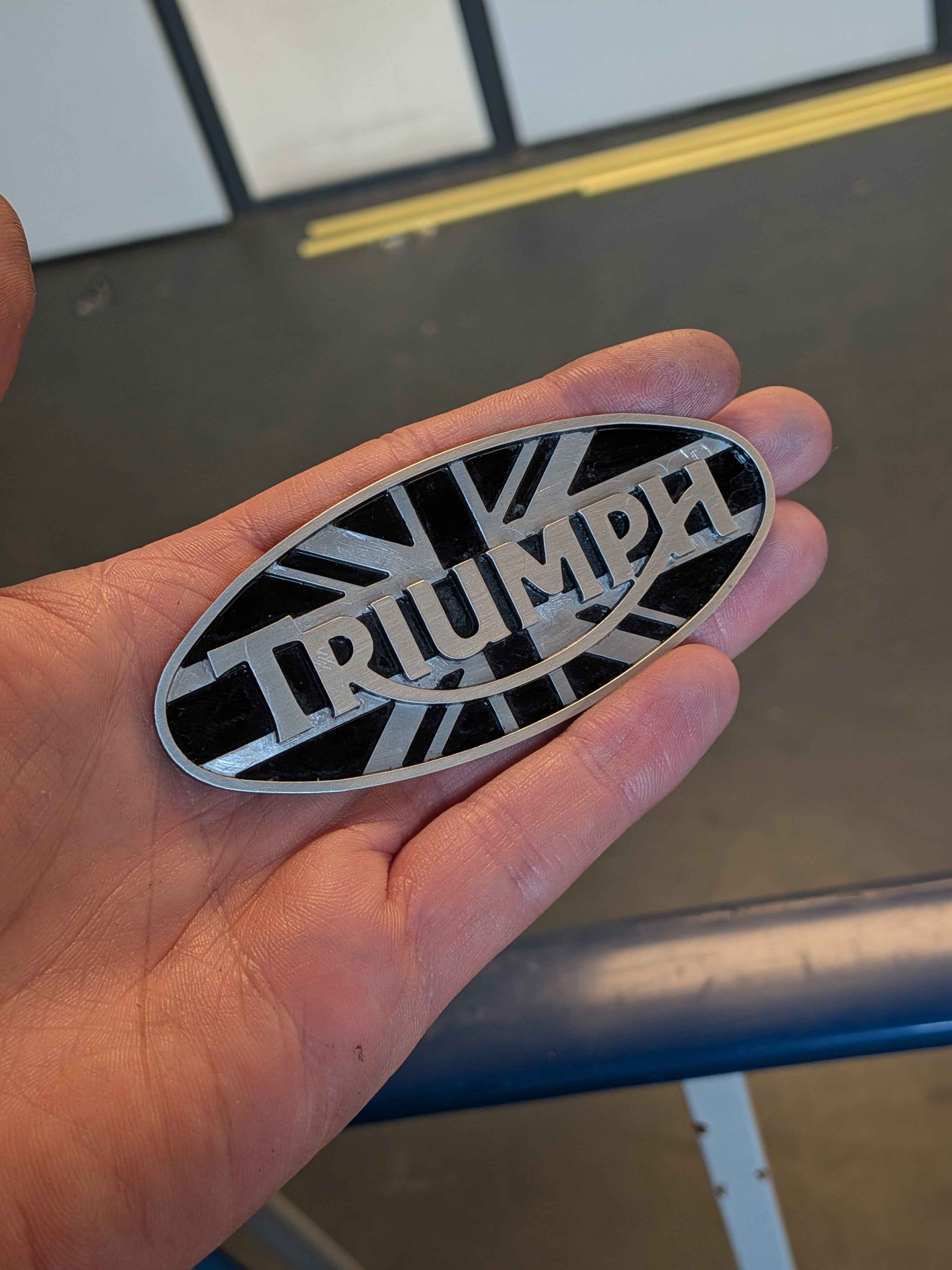
I figured this was a great excuse to machine my own custom version, and how could it get any more iconic than the union jack!
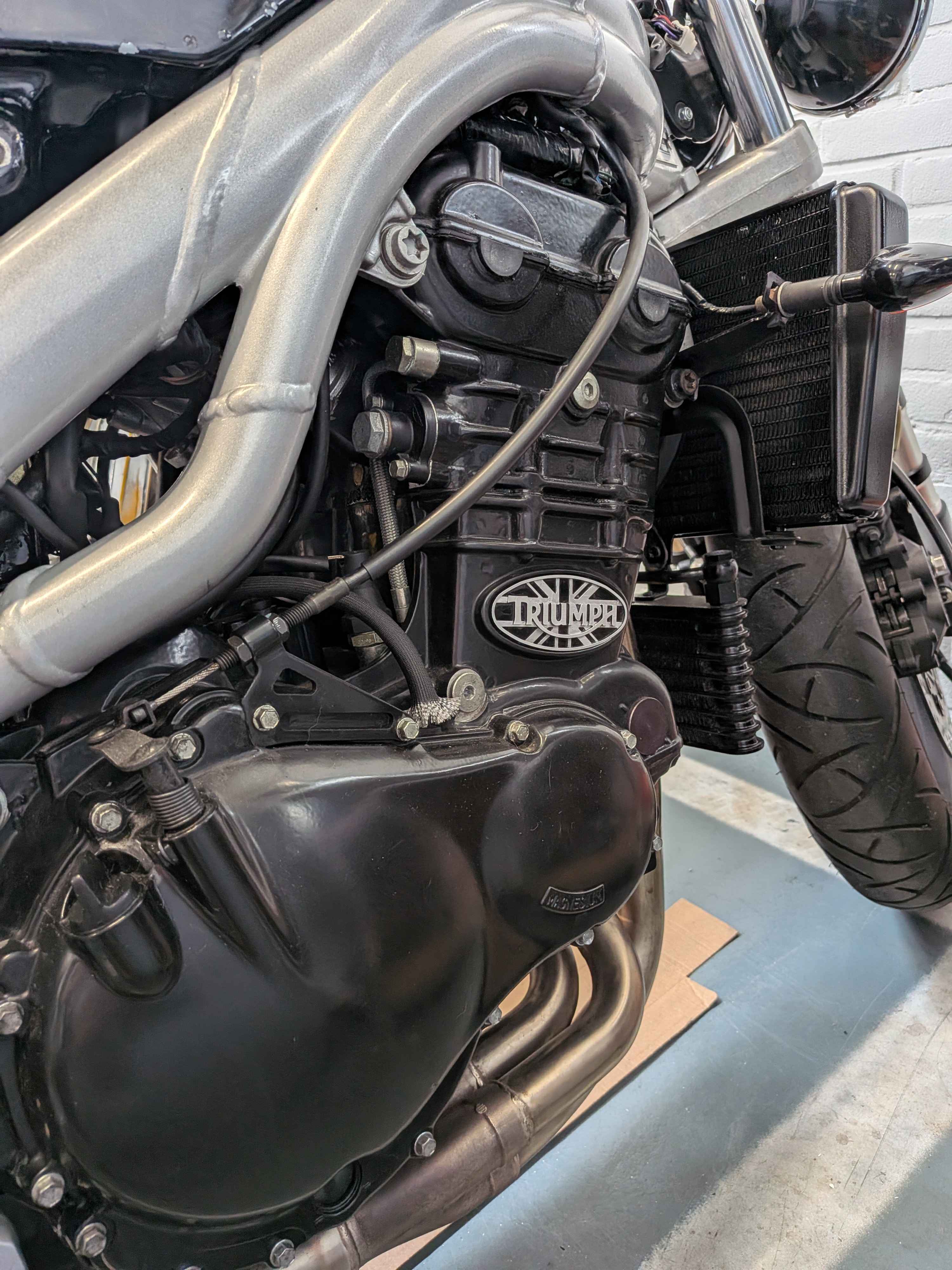
To get the shape just right I ended up taping off the area with masking tape, cut it out carefully with a knife and then scanned it in.
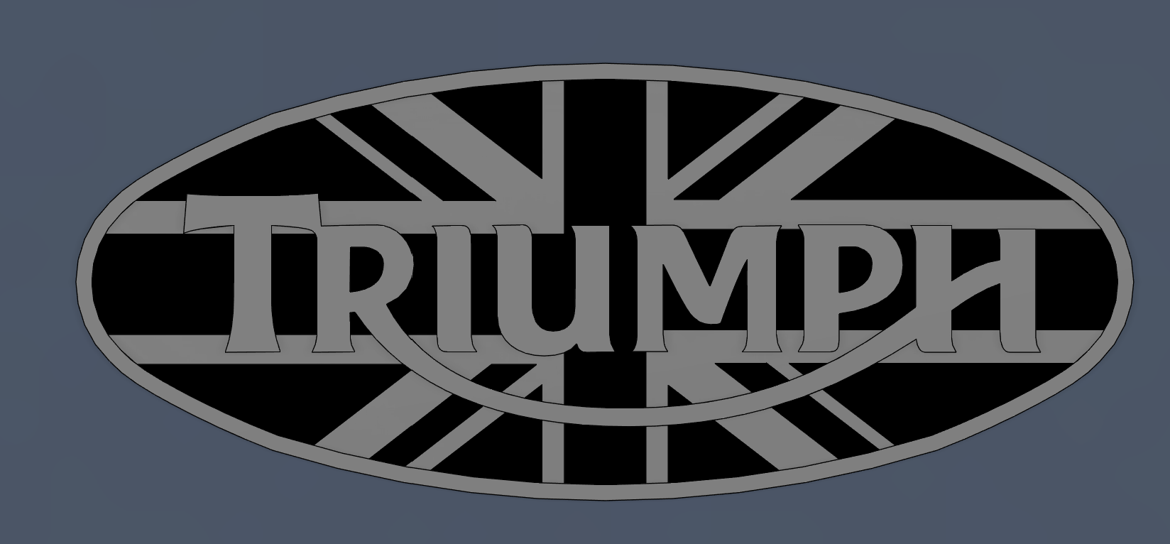
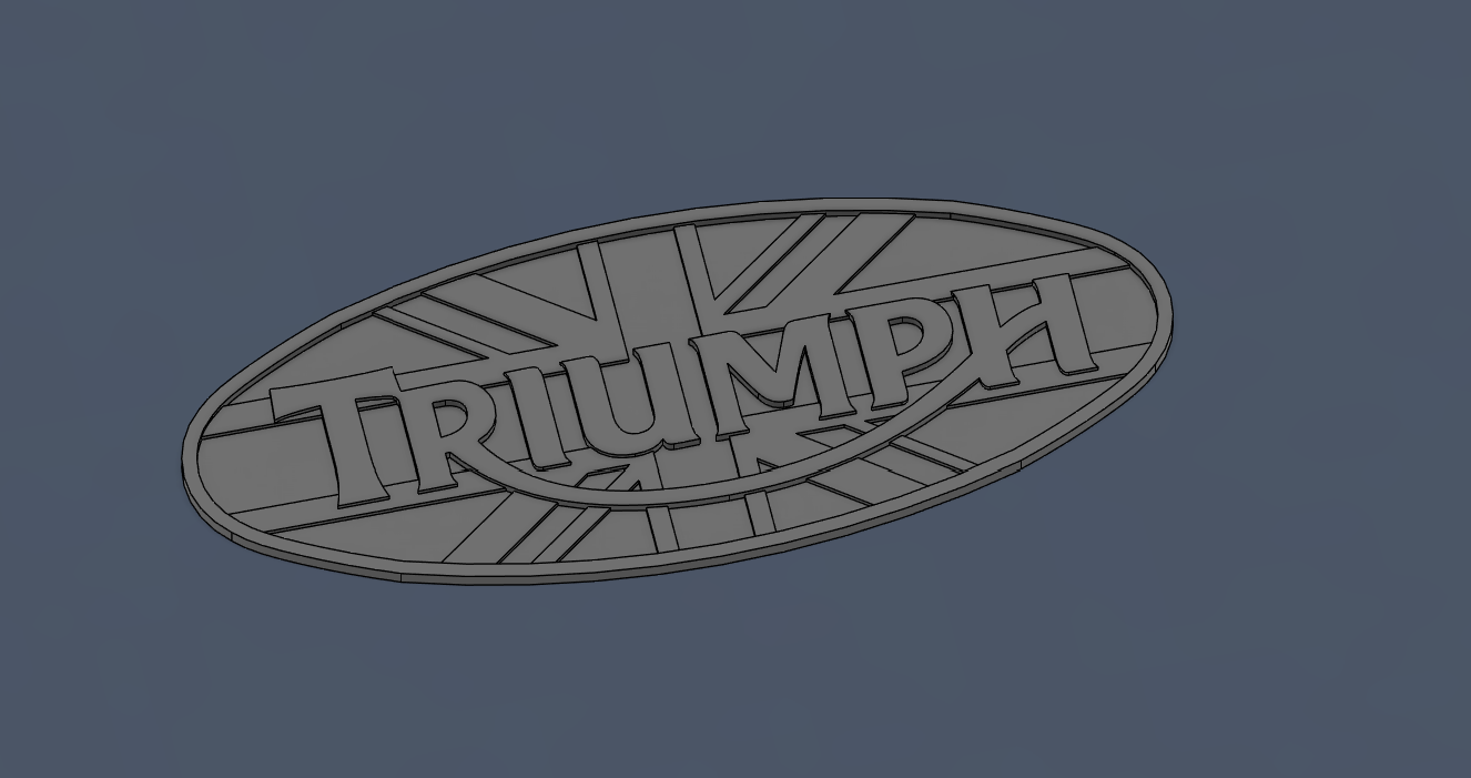
Once scanned in I was able to recreate the shape in CAD and 3D print a prototype.
After 2 attempts I finally got the shape just right! I then machined it out of aluminium, painted it with engine paint and carefully removed all the paint from the raised sections to reveal the union jack underneath.
For removing the paint I used a flat blade and toothpicks as well as cotton swabs with a bit of rubbing alcohol whilst the paint was not yet fully hardened.
To bend the part into the curvature of the engine I just rolled it across a paddock stand by hand gently creating a curvature in the part.
In the future I would probably make a 3D printed jig for the bench vice, but in all honesty this was too much effort for now.
I also included an alternative version that only has the Triumph logo without the union jack.
More photos of the part and production process.
Right click or long press to view full-size image in a new tab
You can find these files here.
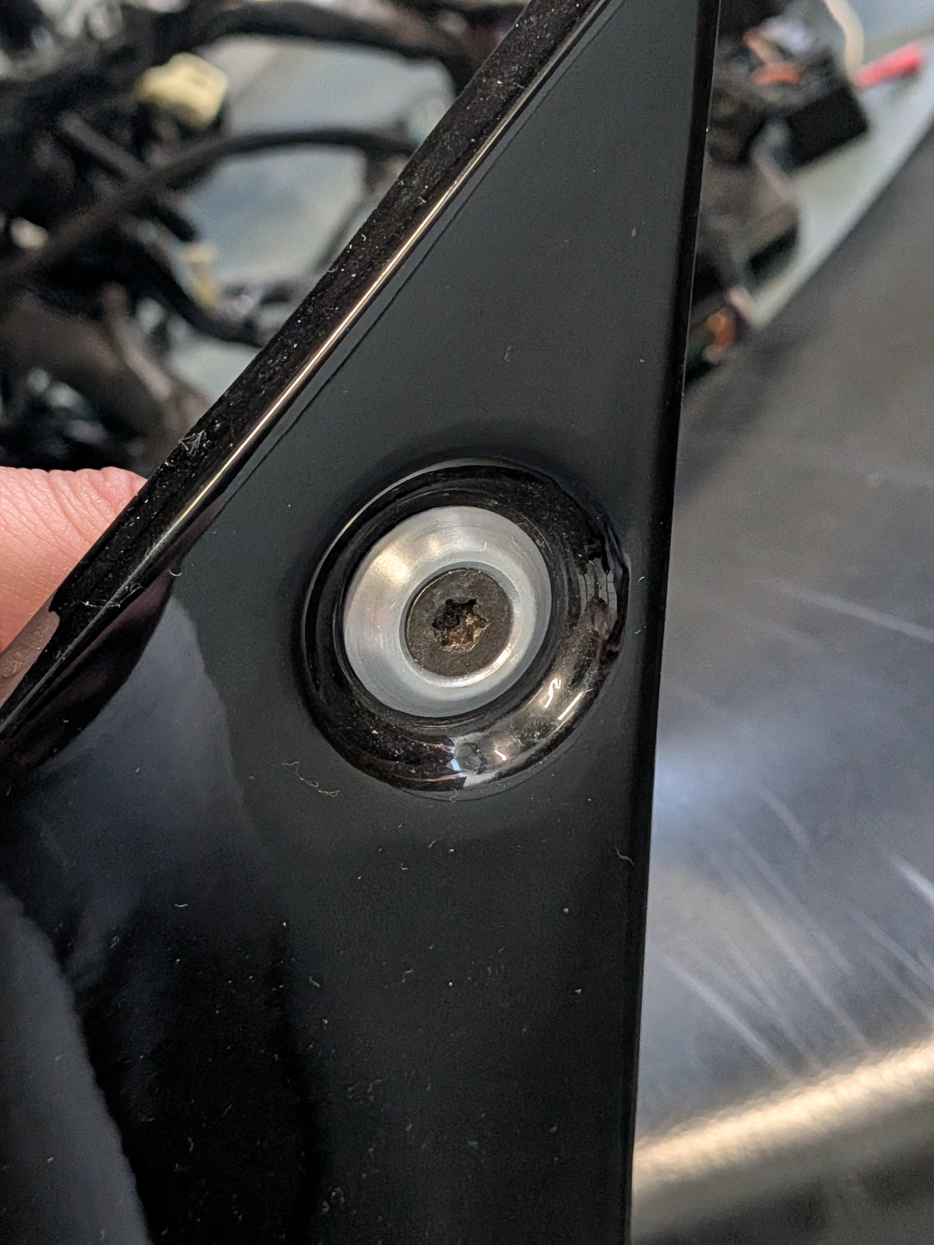
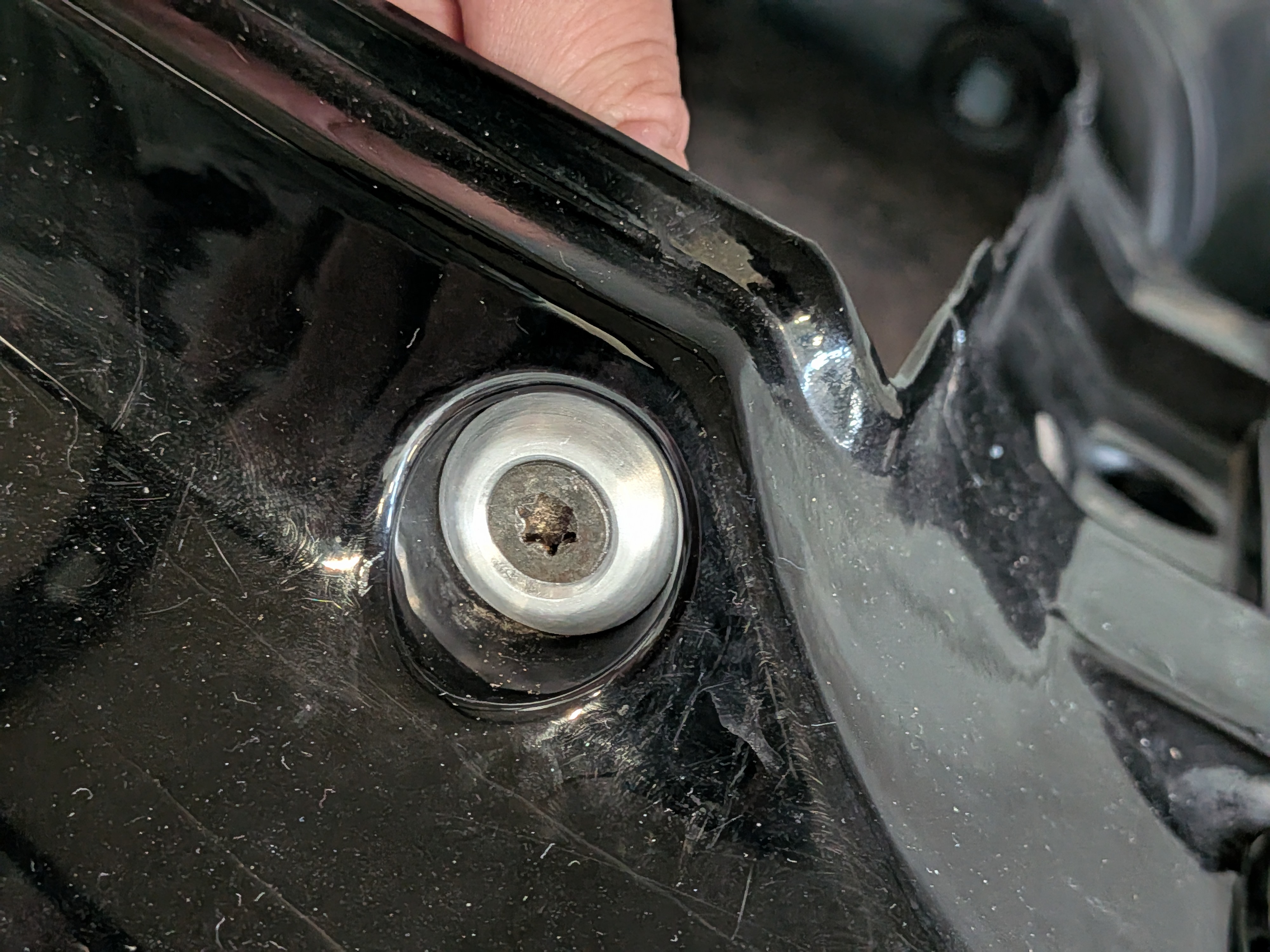
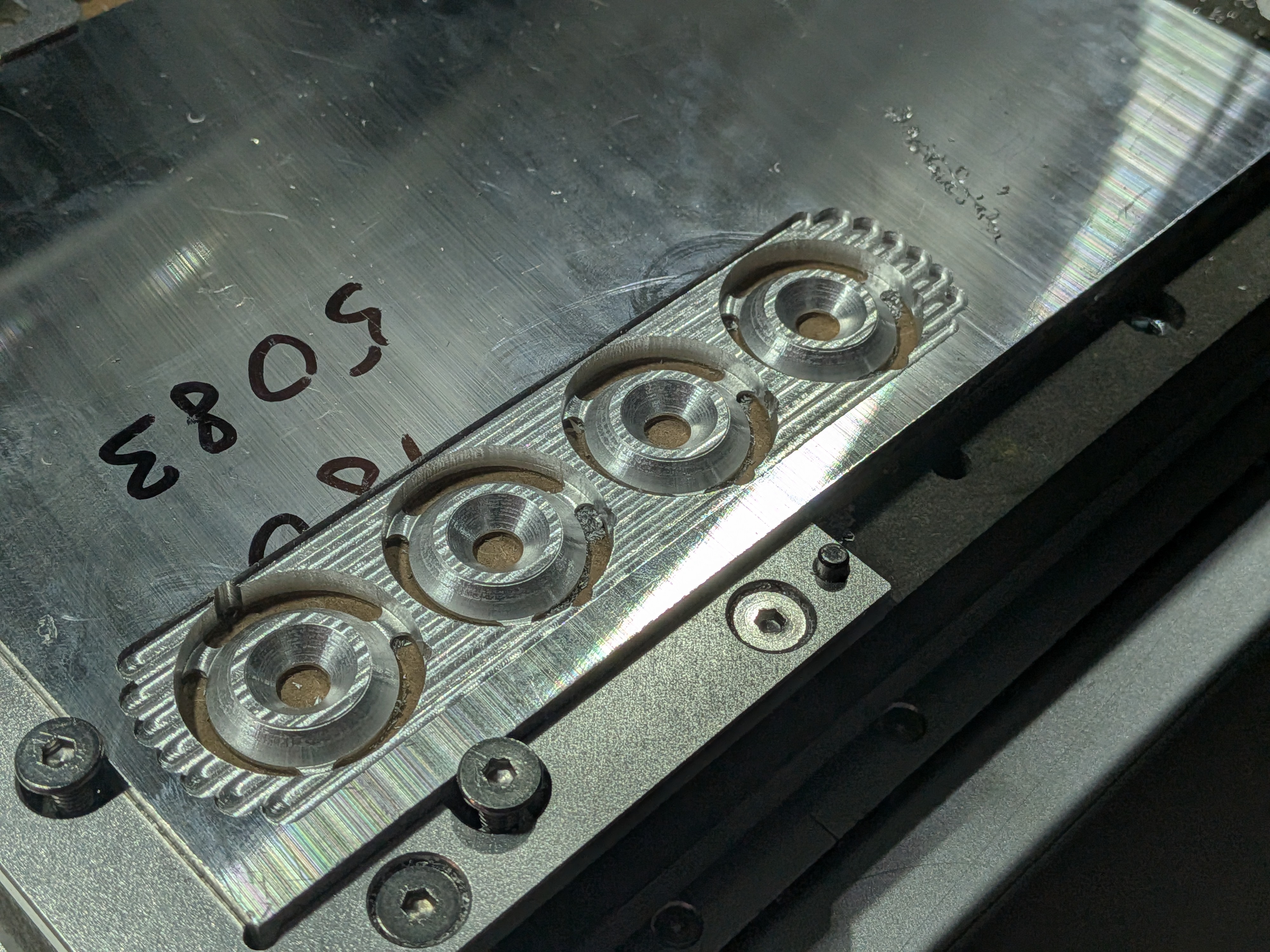
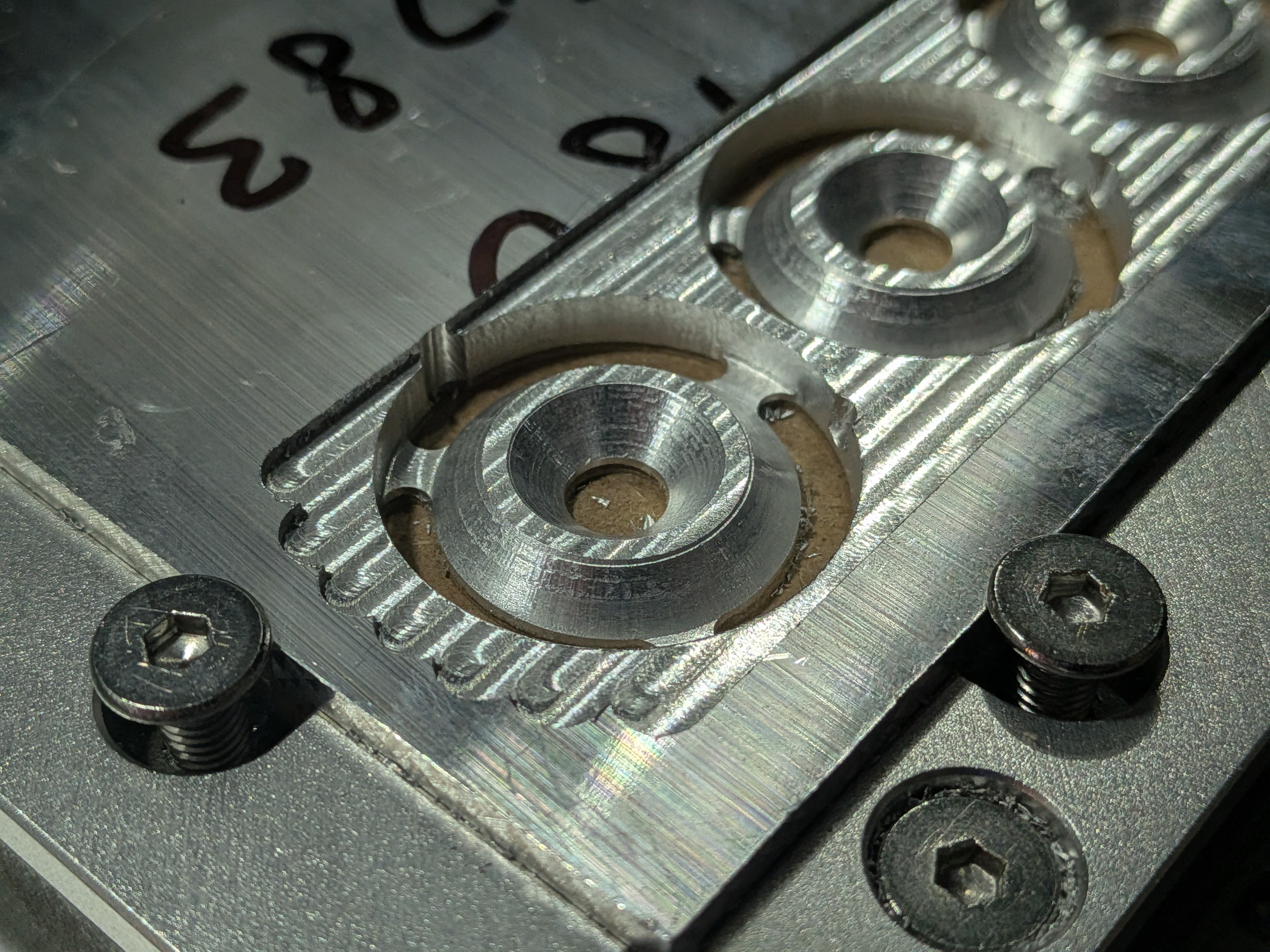
Washers
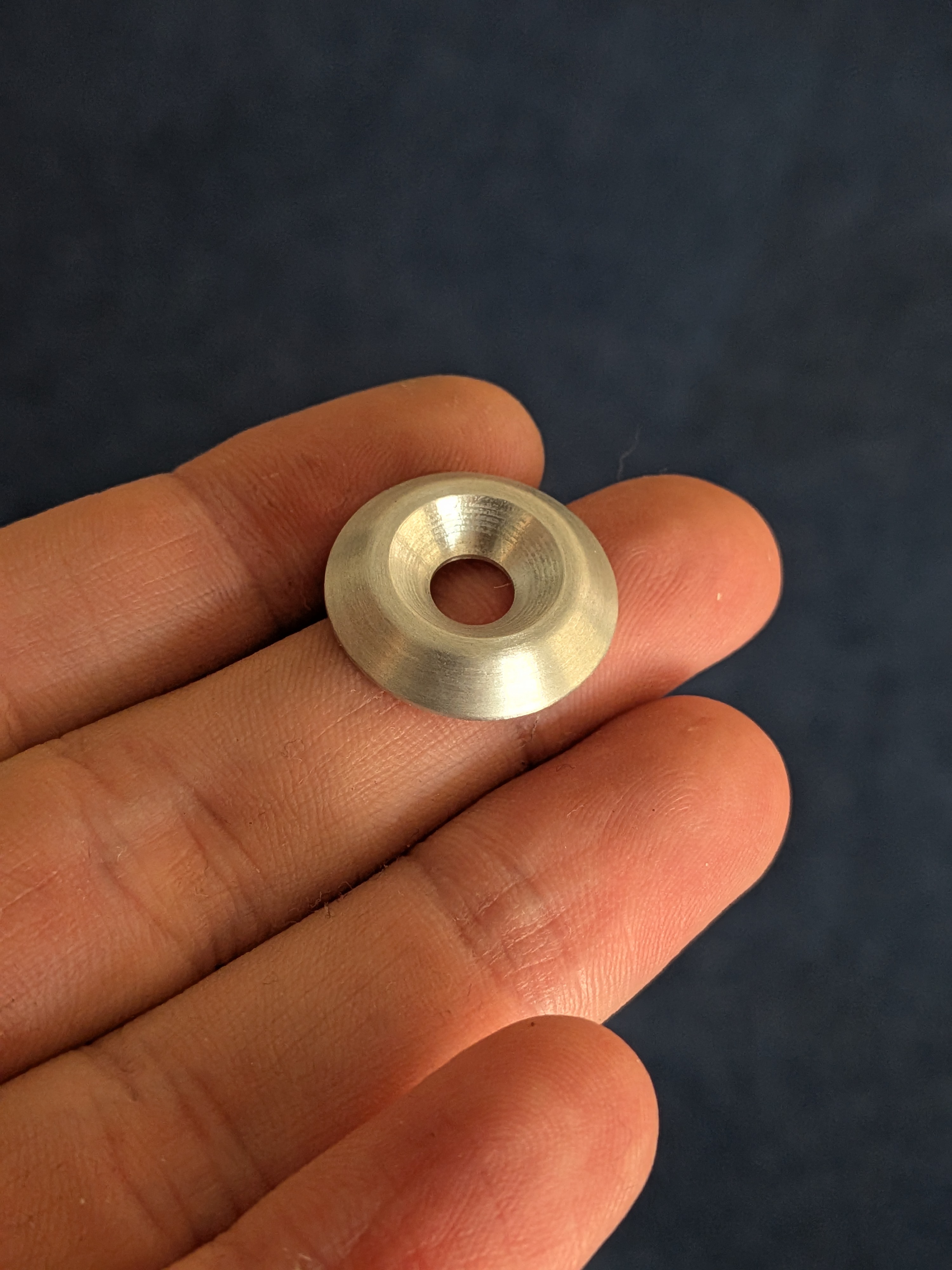
One of the parts lost by the previous owner were those decorative angled spacers/rings that sit between the bolt and the rail fairing of the bike.
Instead of sourcing new ones or buying generic ones I decided why the hell not make them myself (starting to see a pattern here).
So that’s exactly what I did!
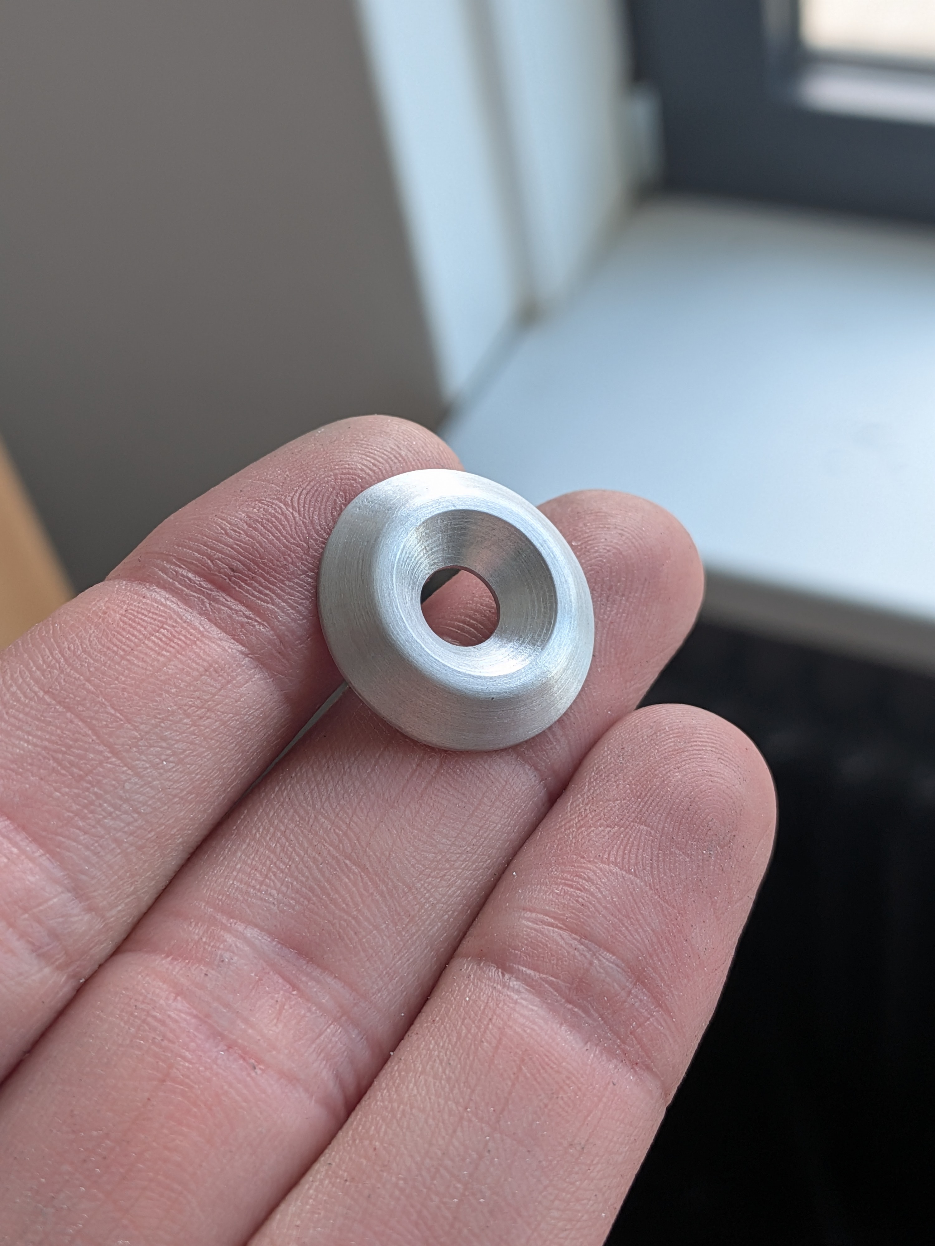
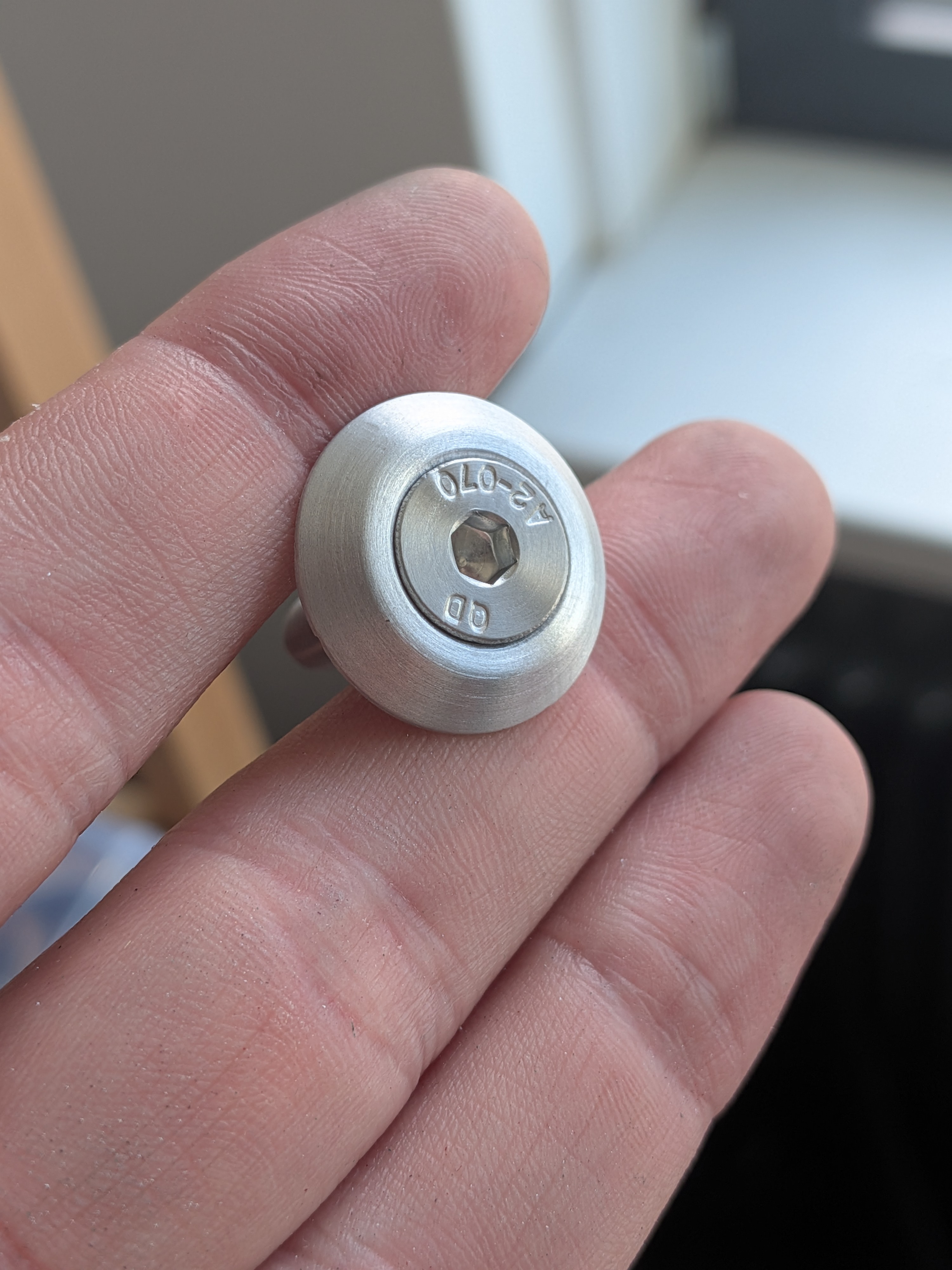
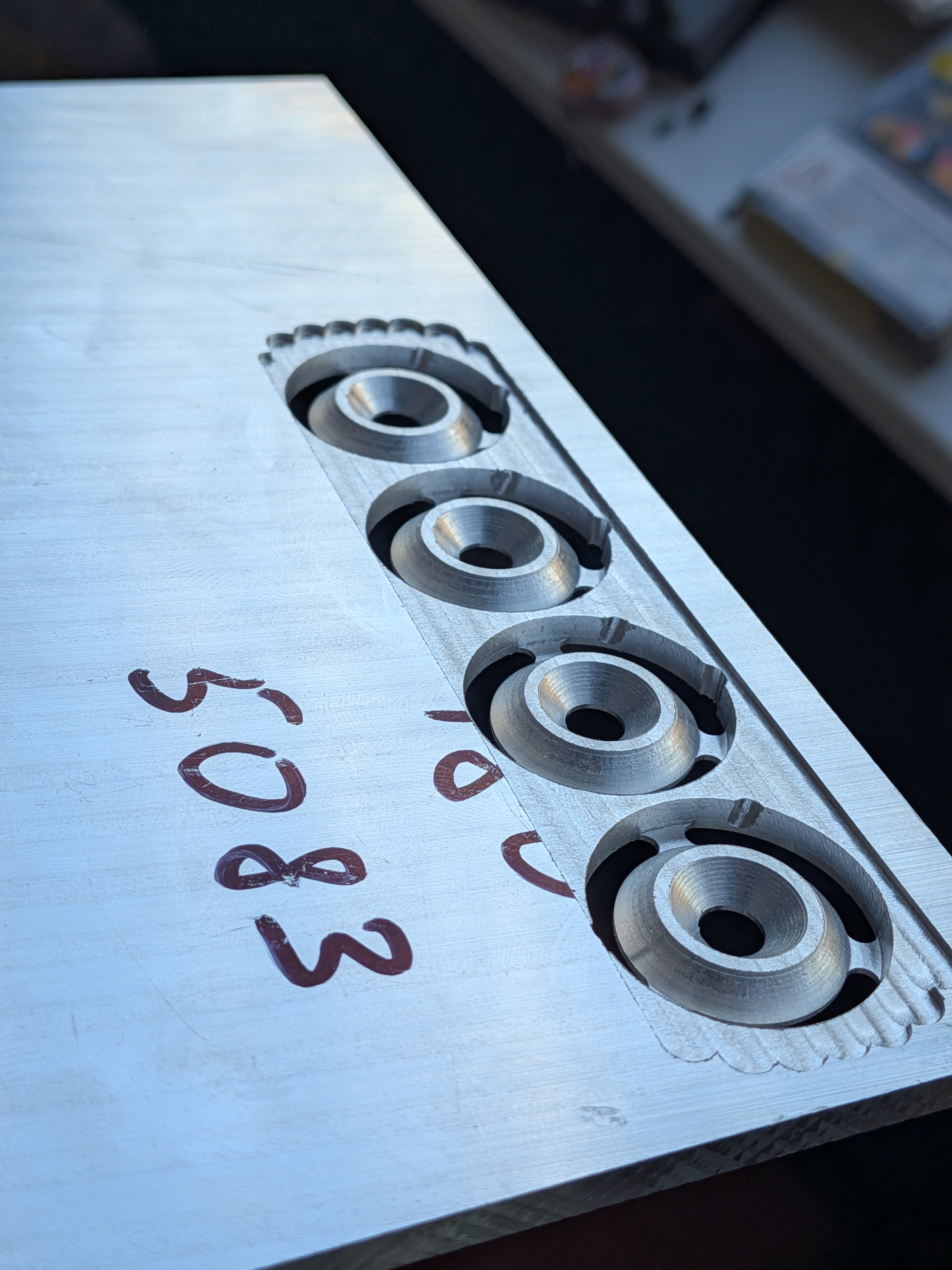
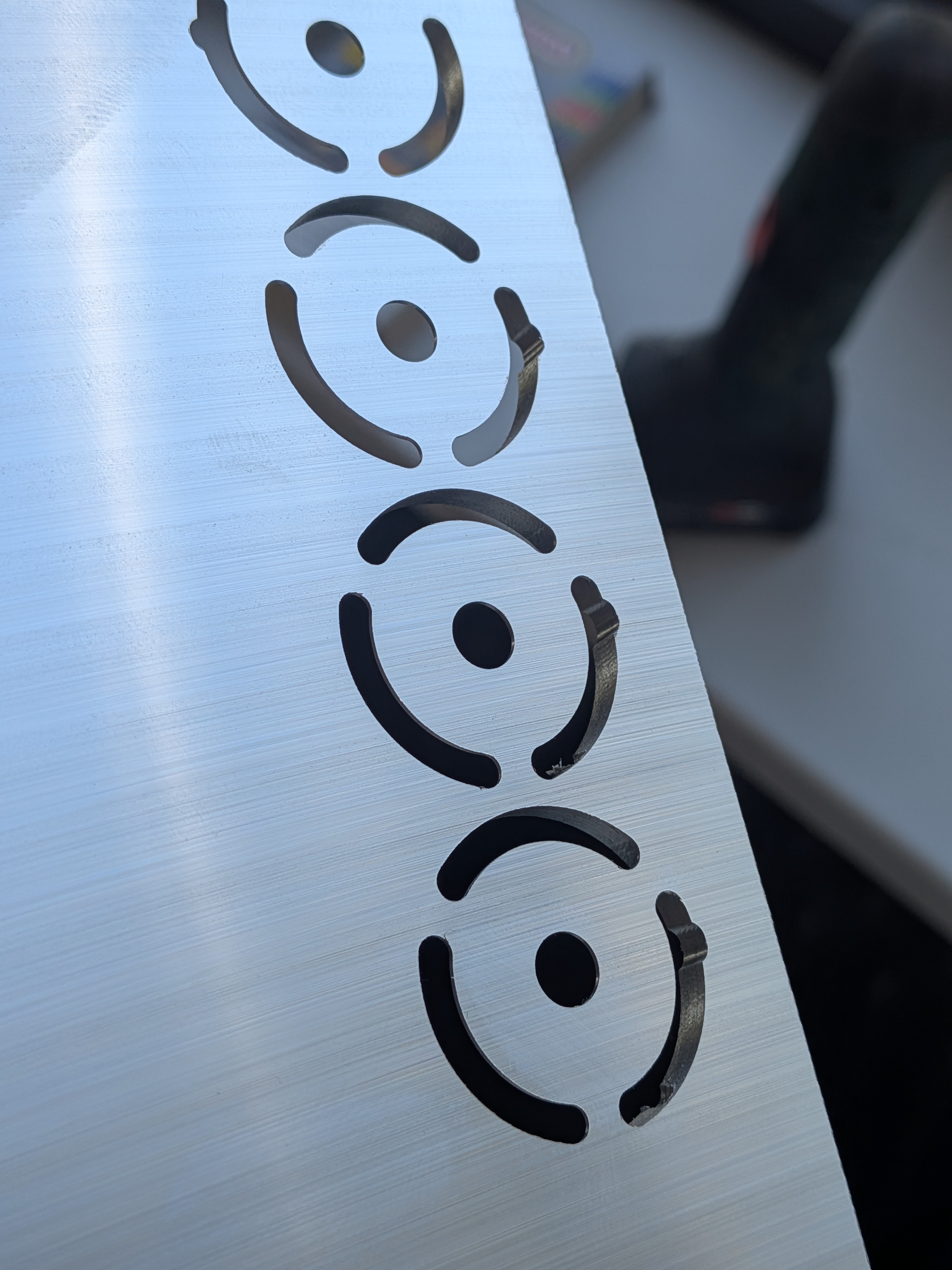
These really aren’t anything too fancy, but it taught me a bunch of new skills with the CNC machine such as: rough passes, rest machining, surfacing a part properly and more!
I had a lot of fun making these and whilst this may not have been one of those items where CNC machining them is cheaper, it was more fun this way.
More photos of the part and production process.
Right click or long press to view full-size image in a new tab
You can find these files here.
Dash Spacers
This particular custom part may not be all that applicable to most people converting their Daytona’s.
However mine came with the LSL superbike kit installed, which for as awesome as it is, also poses it’s own problems.
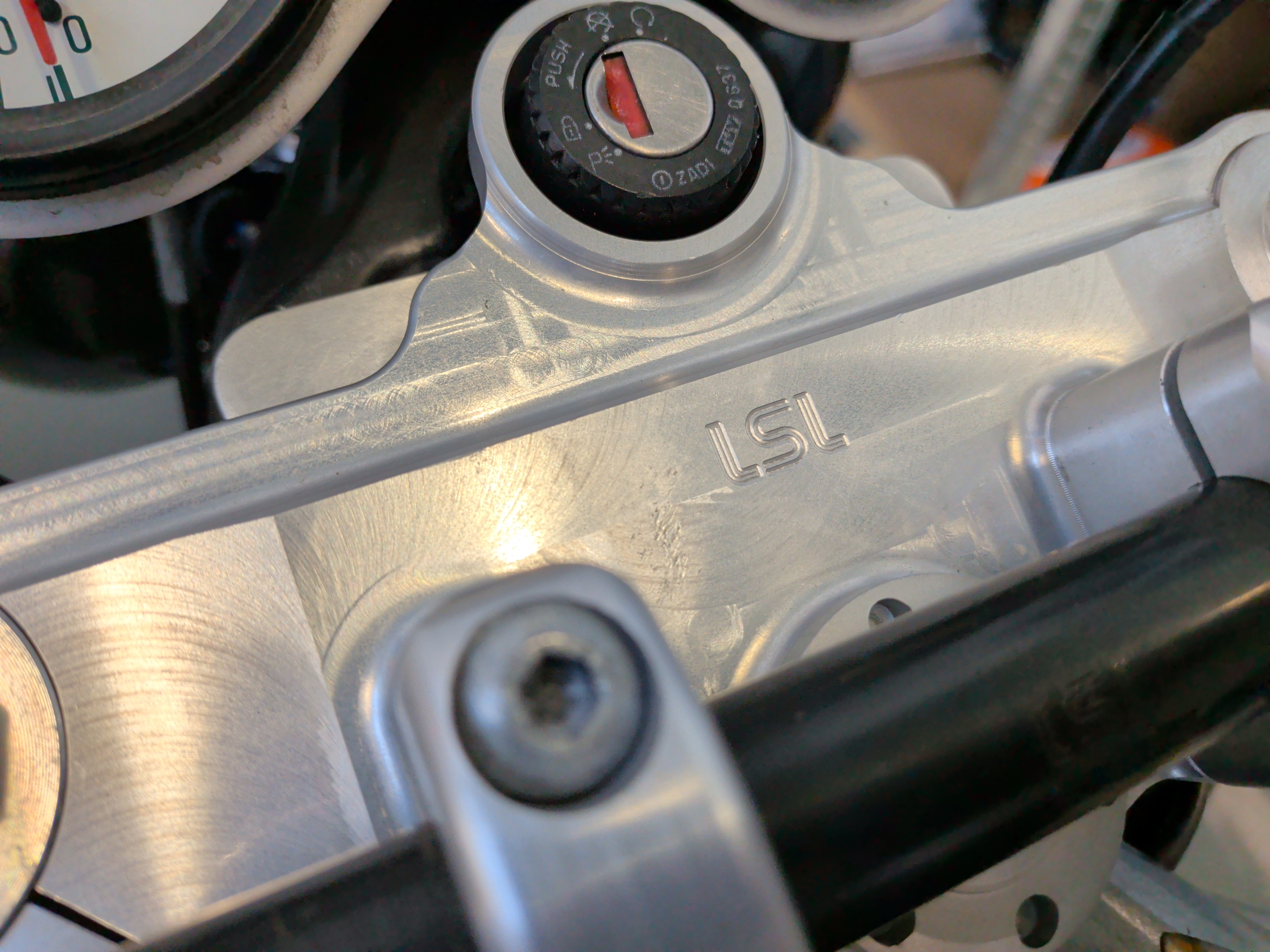
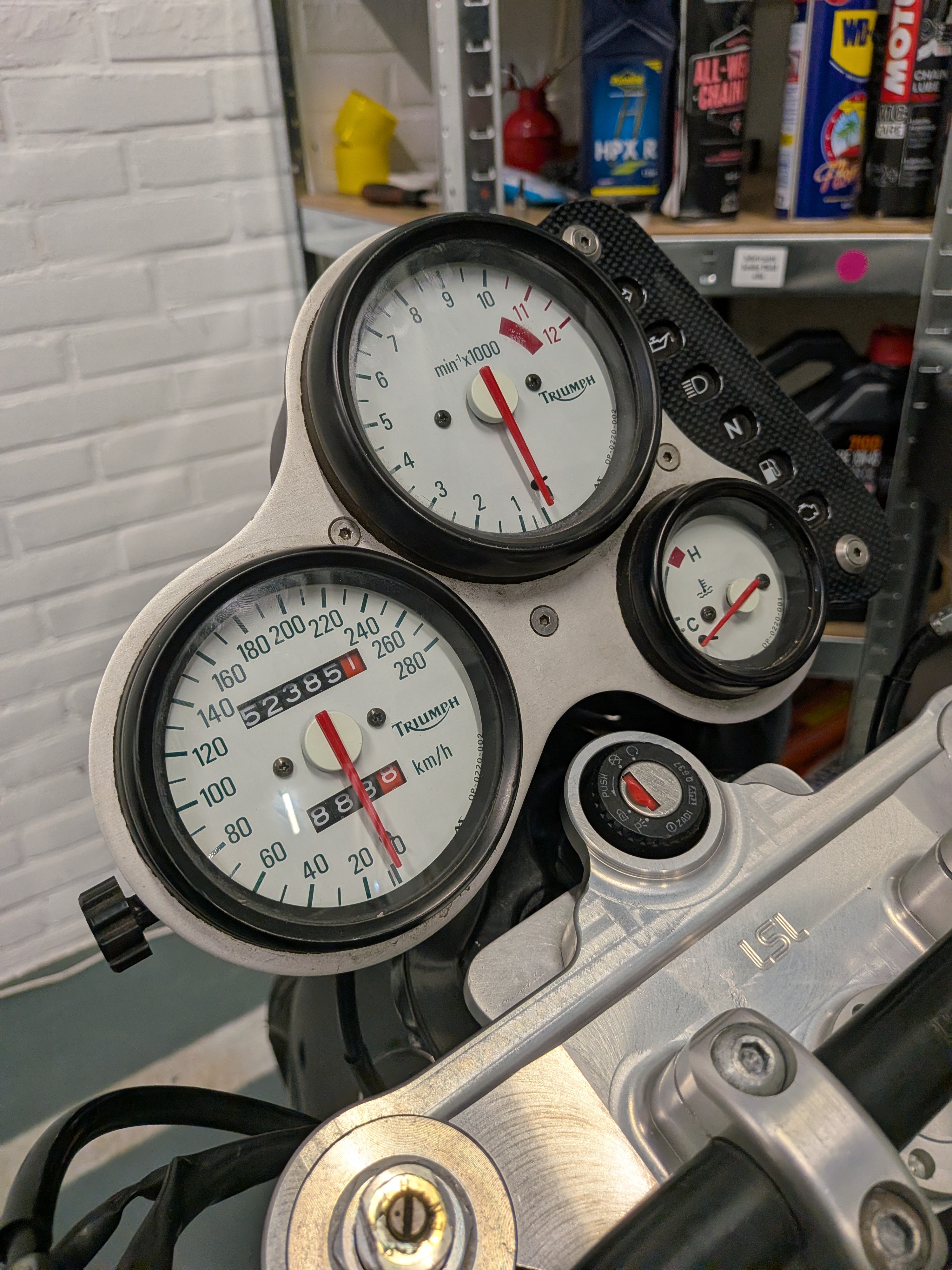
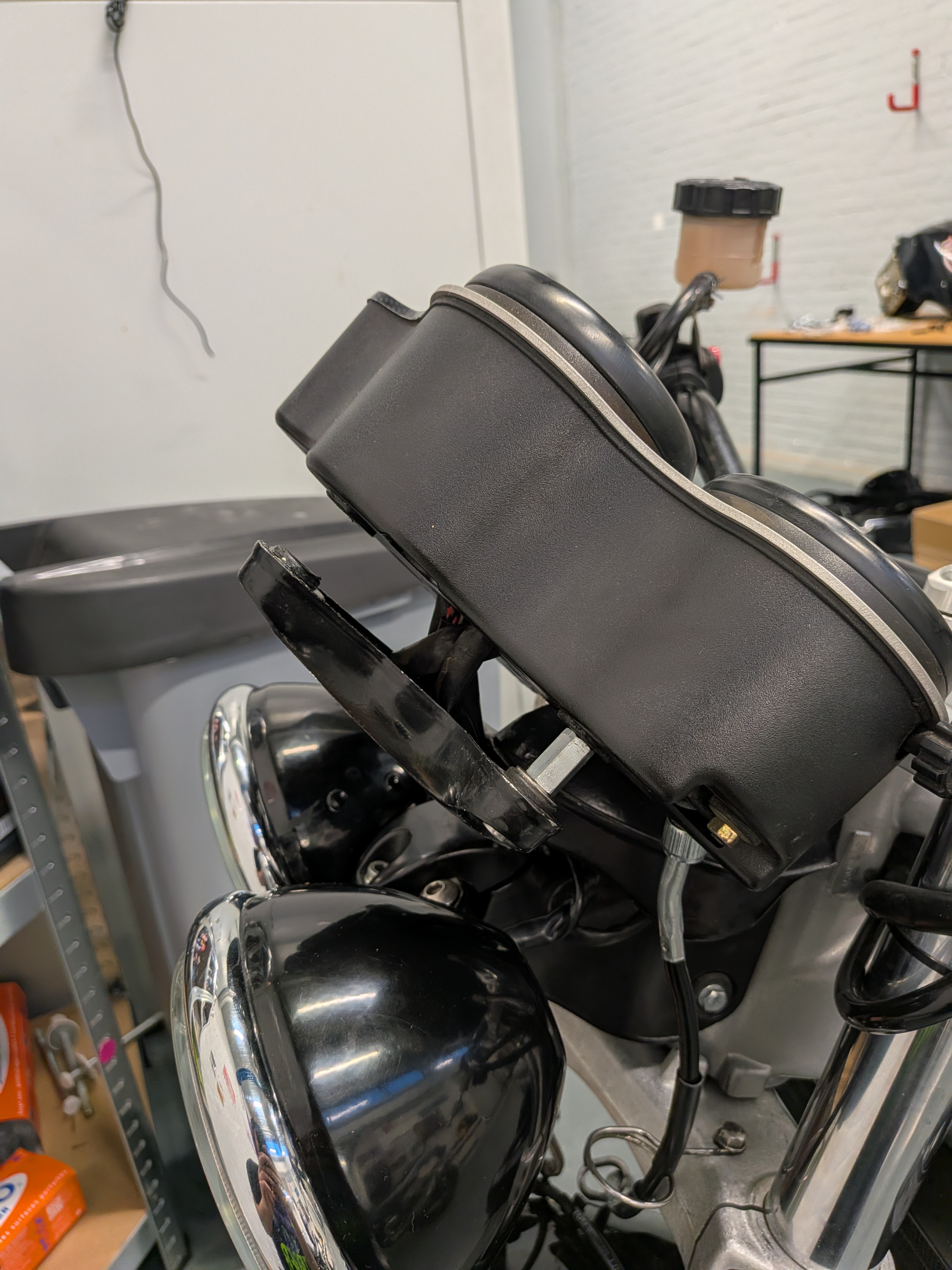
Main issue being the dash mounting solution, as the LSL superbike kit was meant to put regular bars on the Daytona. What I found is that there was some sort of adapter on it to use the Speed Triple dash mount, but as a side effect it lowered the dash by about 1-2cm which caused the speedometer cable to interfere with the headlight bracket.
I am still uncertain if this extra aluminium bracket was from LSL or custom made by the previous owner, definitely not my work but looks nicely done.
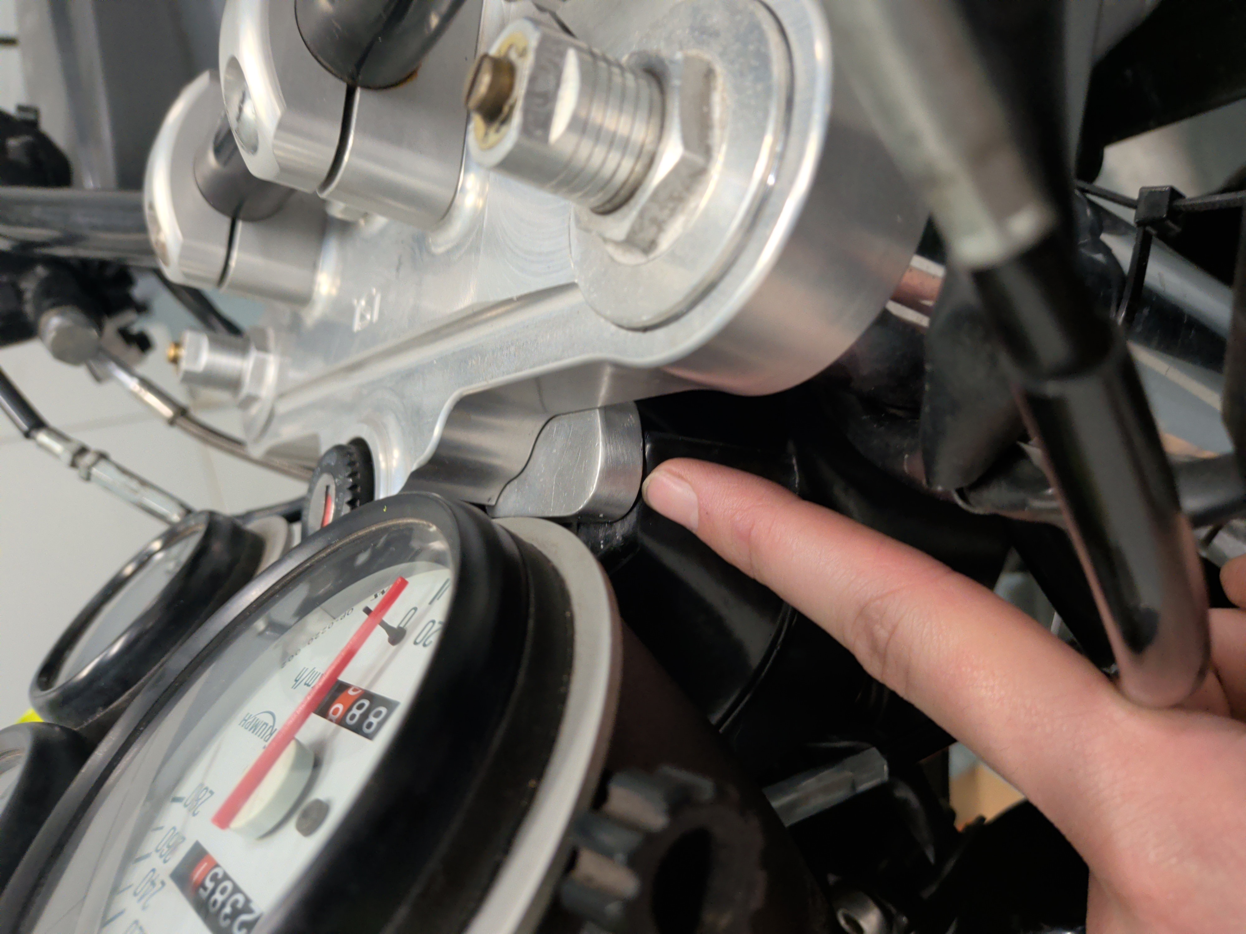
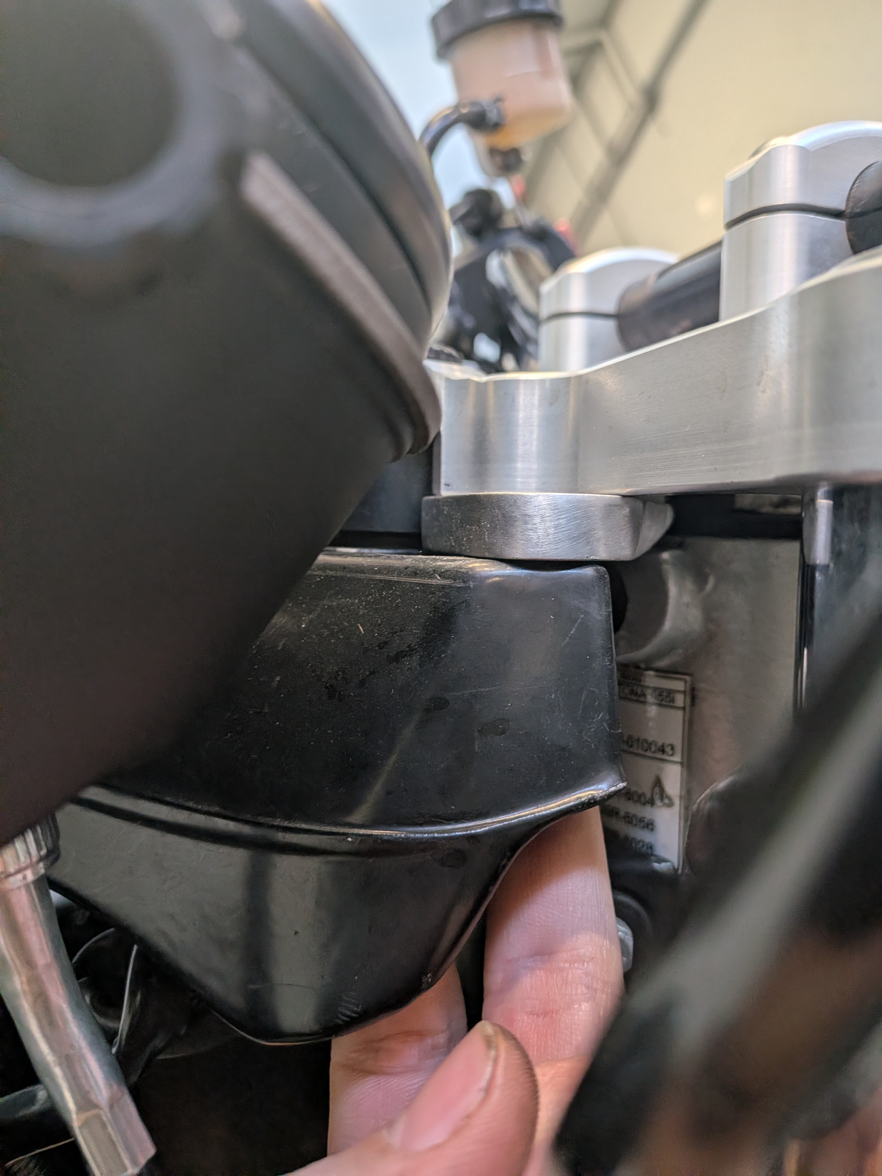
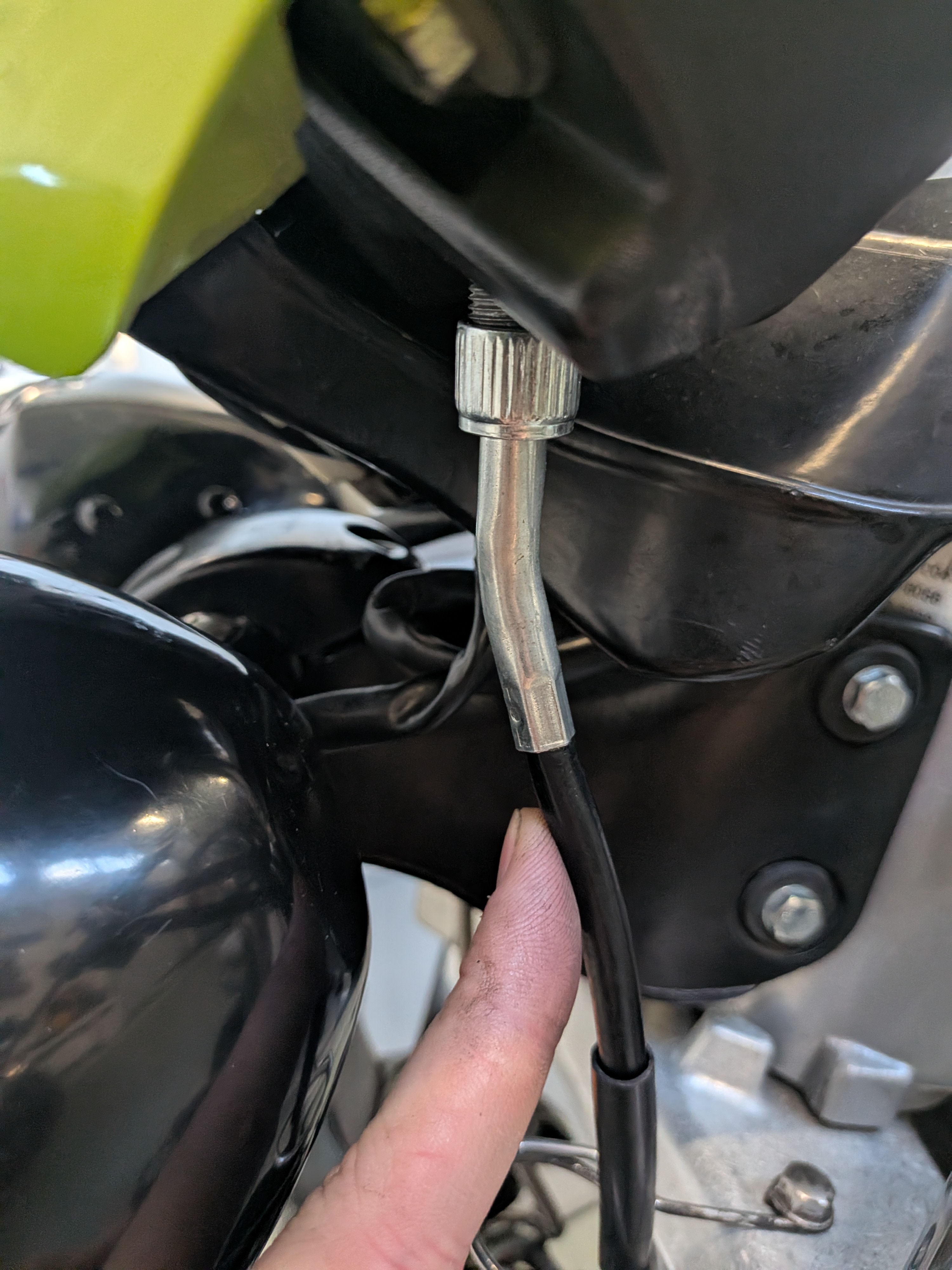
So the main challenge here was that I either make a new bracket which would cause the dash to sit further forward, I make an entirely new top plate for the triple tree which whilst cool is also not something I wanted to do.
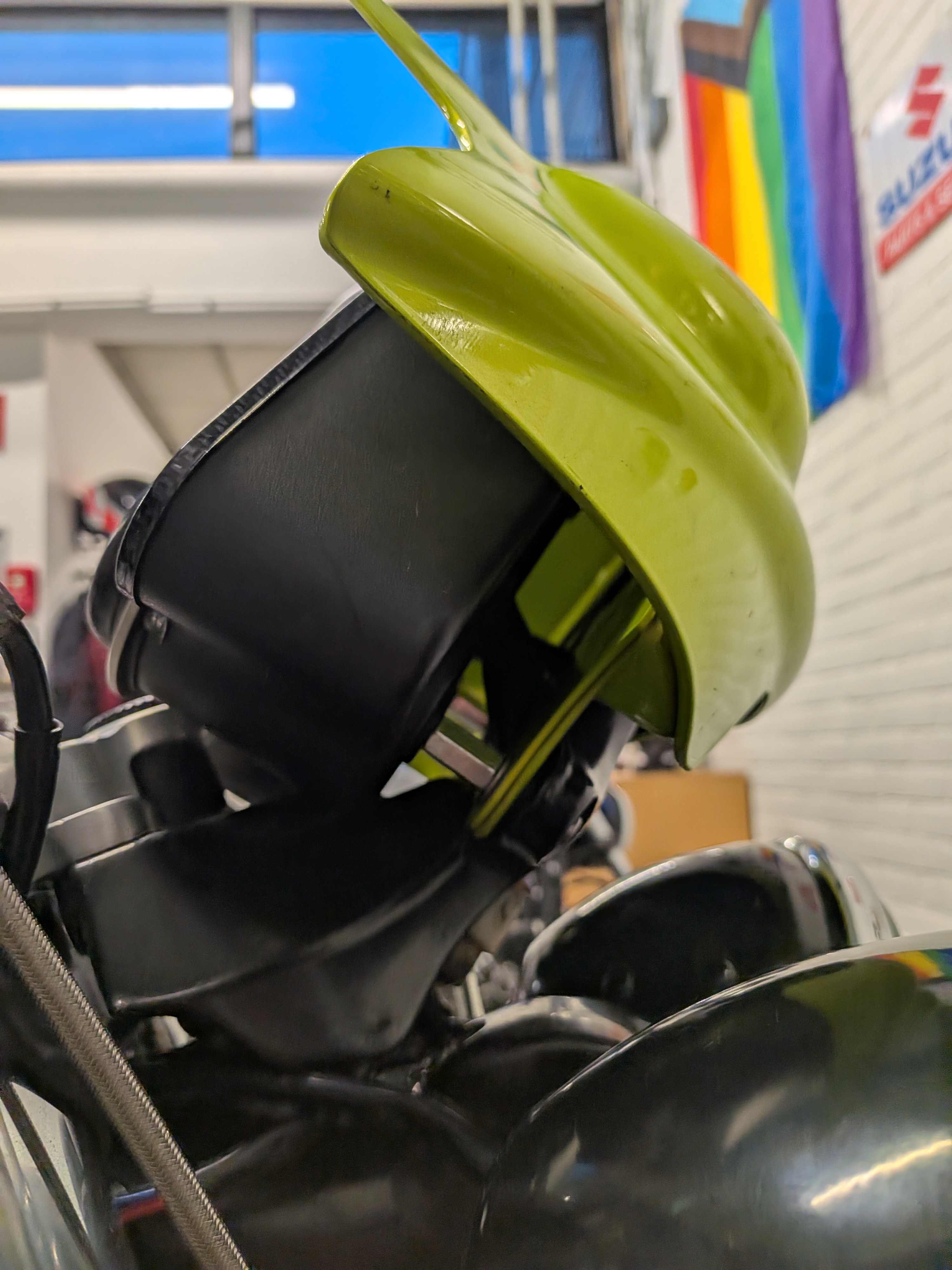
Or the option that I ended up picking which was raising the dash off of the mount with some spacers, which had the added benefit of making it easier to mount the fly screen (for which the mounting hardware up top was missing)
So here is what I came up with:
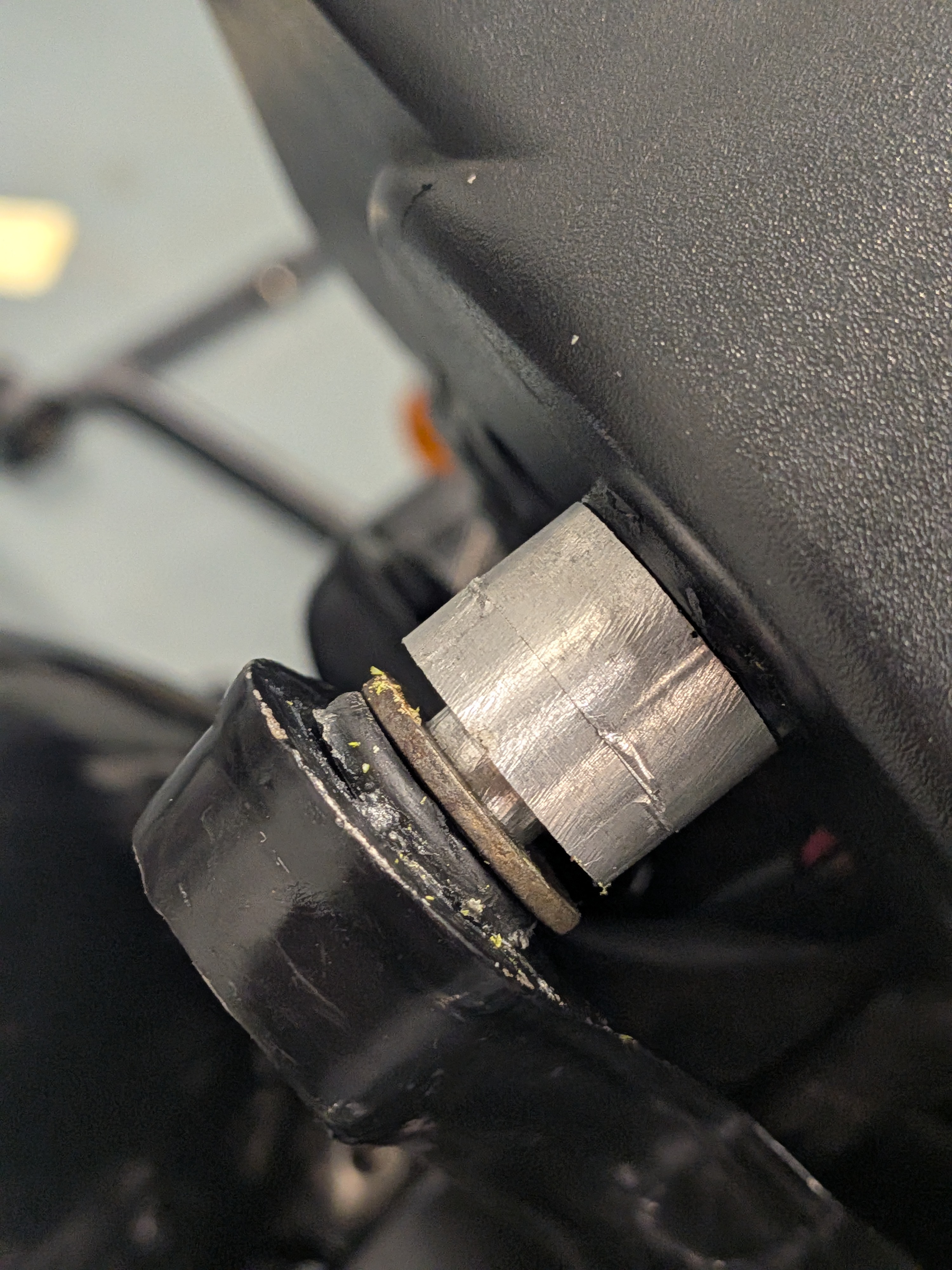
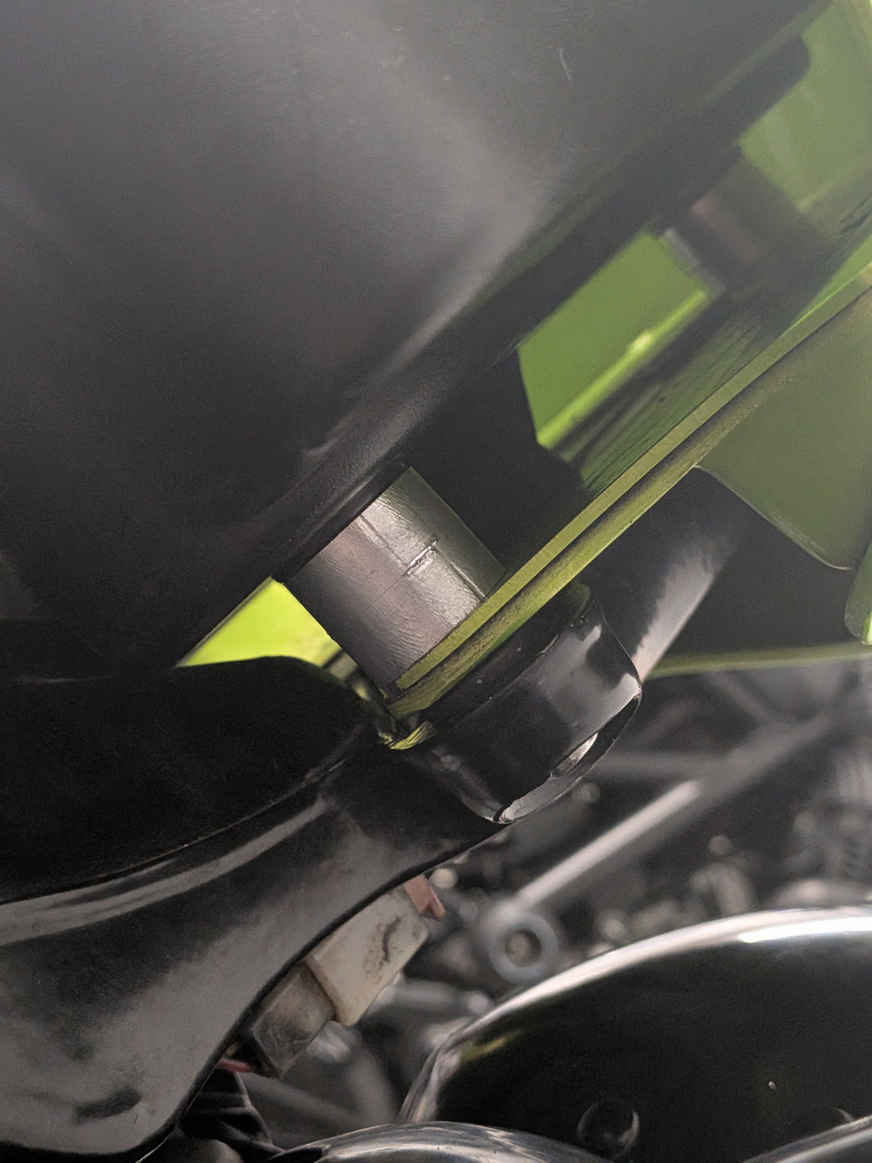
These are simply put just a set of spacers to place the dash further up and clear the headlight bracket.
This puts the dash back in it’s factory position but leaves the fly screen lowered on the bike creating a more aggressive styling reminiscent of later Triple models such as the 675.
Due to me not having the required stock to make these parts in one go (thickness wise) I spli them into 2 pieces. You can just use 2 stacked on top of eachother for the bottom 2 bolts and use 1 normal one, 1 spacer with the cut out/narrow section and a washer as shown in the pictures.
This allows you to slide on the fly screen as expected and secure it down with the bottom 2. You will of course need longer mounting hardware for this.
Whilst you could just use generic spacers (as I did for testing in some of the extra photos) I figured this solution was cleaner and more secure in the long run.
More photos of the part and some of my experimentation.
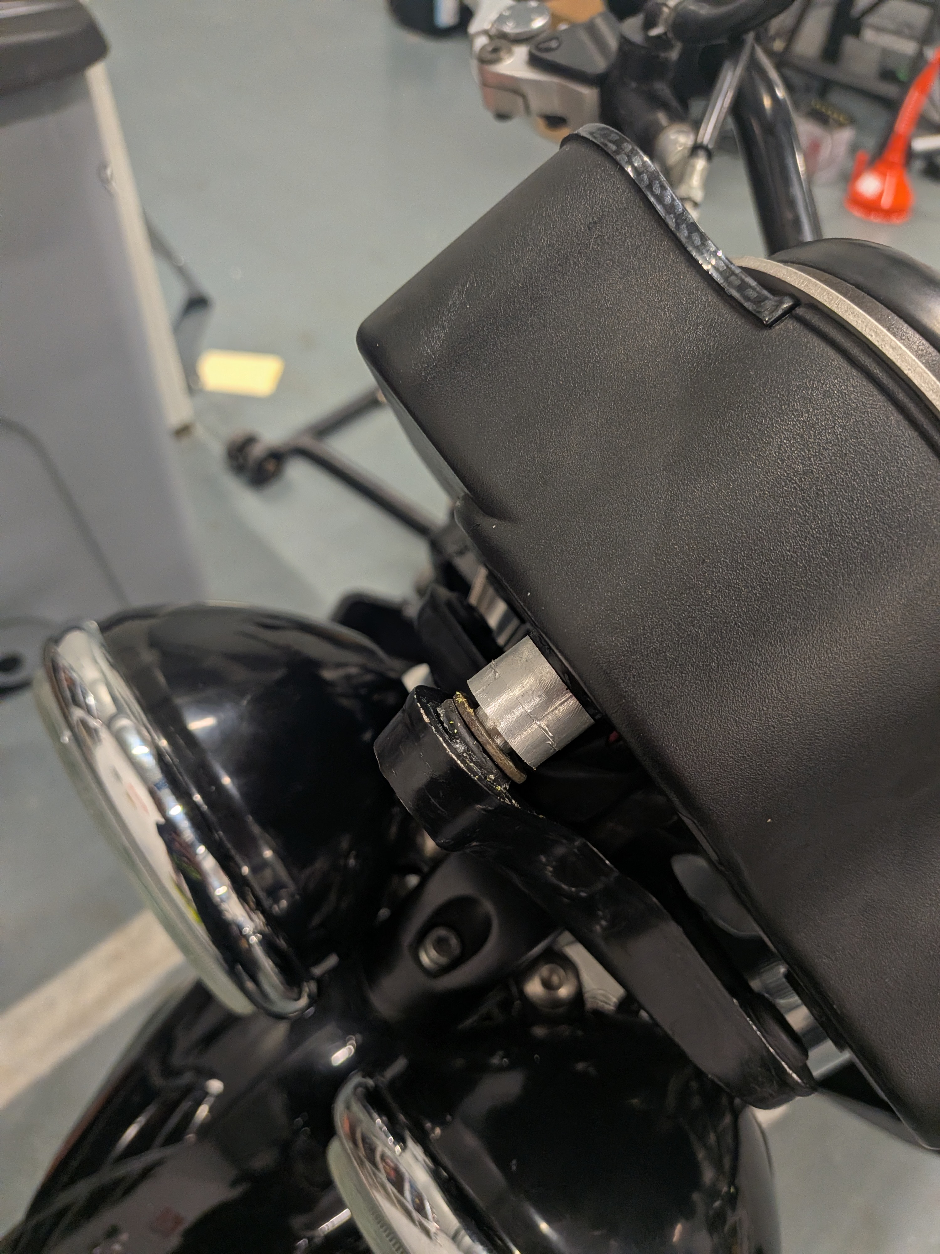
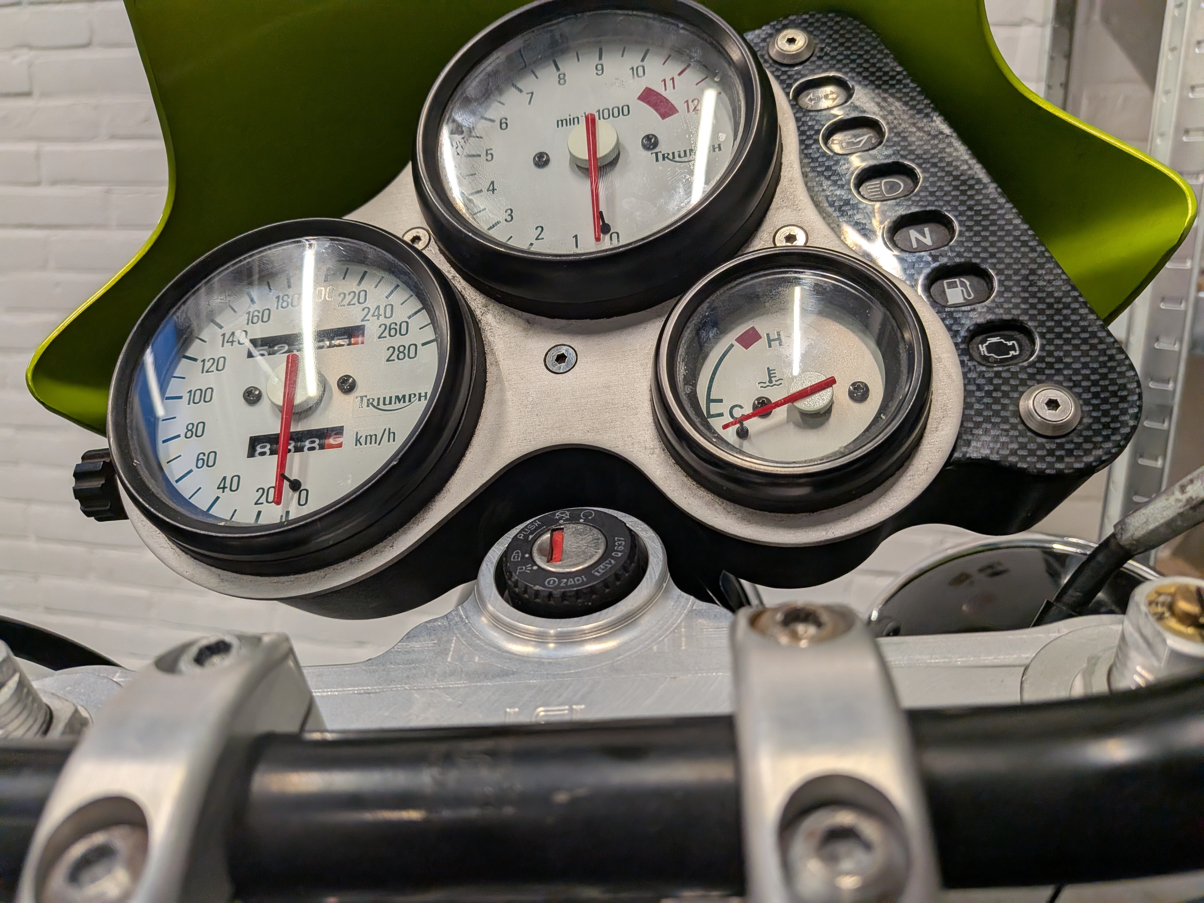
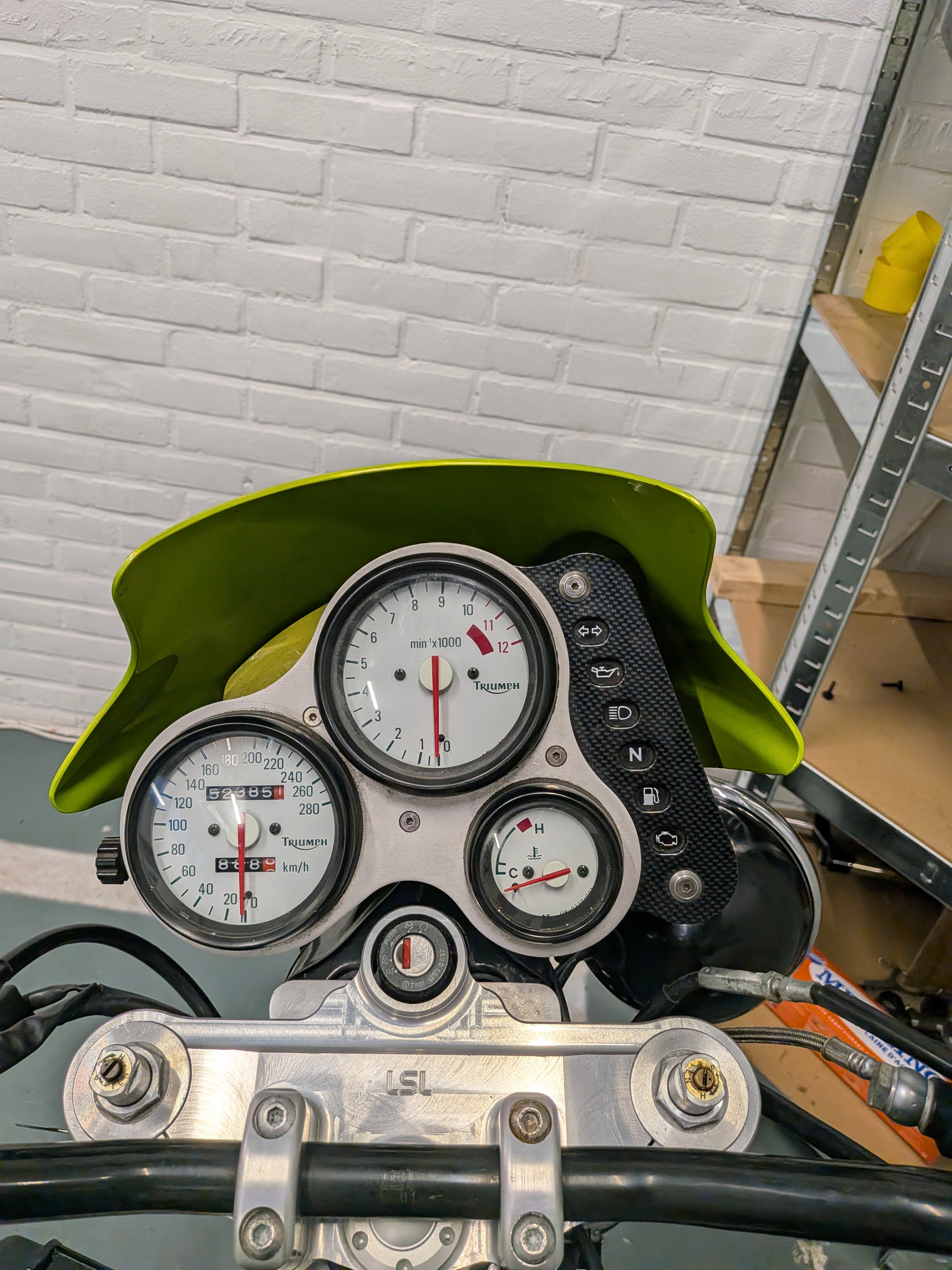
Right click or long press to view full-size image in a new tab
You can find these files here.
Current To-Do and future plans
Current To-Do list (in no particular order):
- New Tires
- New fork seals
- Suspension adjustment
- Fit missing vent/overflow hoses to tank
- Seal tank
- Paint bike
- Balance throttle bodies
- Check/Rebuild brake calipers
- New fuel lines
- New vacuum hoses
- New breather hoses
- New coolant hoses